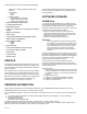
S7999B, S7999C SOLA Local Operator Interface PRODUCT DATA • From behind into a panel cutout (5.45 in. W X 4.3 in. H) using 4 #6-32 screws, nuts and 4 standoffs (provided). Wiring connections to the S7999C are made via a 4-pin connector on the back of the display. NOTE: If display S7999B is used to monitor a lead/lag system, display S7999C can NOT be used. FEATURES • Individual boiler status, configuration, history, and diagnostics.
S7999B, S7999C SOLA LOCAL OPERATOR INTERFACE — MMC Port for installing software upgrades (when required) — LED indicators: • Power • COM — Models available: • S7999C1008 has white border • S7999C1016 has blue border • S7999C1040 has black border • Allows for lead/lag commissioning. Use the Product Data Sheet for the Sola Controls (form 650303) as a guide and explanation of the parameters that are being programmed.
S7999B, S7999C SOLA LOCAL OPERATOR INTERFACE Storage/Shipping Temperature: -40°F to 158°F (-40°C to 70°C). The software upgrade is automatic after the above steps. The OI Display connects to the Honeywell server, which verifies the configuration file, erases the old application and downloads the new one. Humidity: 85% maximum relative humidity. The OI Display may have difficulty finding the new configuration file at first. In this case, the procedure automatically starts over again until it works.
S7999B, S7999C SOLA LOCAL OPERATOR INTERFACE required to correct the interference at his own expense. COM2 (a) COM2 (b) 2 N/C 1 N/C Read all documentation carefully and respond appropriately to all error messages. COM1 (a) The OI Displays contain software that incorporates many features that are designed to guide you safely through the commissioning process. Safety, however, is your responsibility.
S7999B, S7999C SOLA LOCAL OPERATOR INTERFACE Table 1.
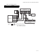
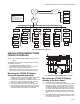
S7999B, S7999C SOLA LOCAL OPERATOR INTERFACE S7999B 120 VAC L1 L2 MEAN WELL S-25-12 POWER SUPPLY AS SYSTEM DISPLAY COM1 NEUTRAL (L2) N 120VAC (L1) L COM2 1 2 3 4 5 6 7 8 9 +12 +12 GND (C) (B) (A) N/C N/C (A) (B) EARTH GROUND 12 DC OUT + V+ DC OUT (COMMON GND) V- 2 VADJ A WIRING KEY C A 1 DO NOT CONNECT THE S7999B TO TERMINALS 1 2 3. THIS WILL RENDER THE DISPLAY INOPERABLE. 2 DISPLAY CAN ALSO BE CONNECTED TO MB2; A, B, C AND THE SOLA SLAVES NEED TO BE WIRED TO MB1.
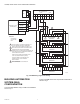
S7999B, S7999C SOLA LOCAL OPERATOR INTERFACE BAS COM 2 COM 2 COM 2 S7999B S7999B S7999B COM 1 COM 1 COM 1 1 SOLA 1 2 SOLA UP TO 8 SOLAS 3 5 4 SOLA SOLA 1 SOLA EACH SOLA IN THE BAS WILL HAVE A DIFFERENT MODBUS ADDRESS. M32006 Fig. 5. S7999B in a Building Automation System. If the screen is dim, check the pin 1 and 2 wiring connections. BAS Modbus message timeout should be set to 1.0 seconds or higher. This means it could take up to 1.
S7999B, S7999C SOLA LOCAL OPERATOR INTERFACE • Gray and crossed out: communication error (disconnected or powered off) Up to 8 Systems can be displayed on the Home page. The name of each boiler is displayed next to the Sola icon button. When Lead Lag is enabled, the system header temperature and firing rate are displayed for each System. When the burner is in standby or not firing the firing rate is not displayed. NOTE: The boiler name may be cut off on the Home page when all icons are present.
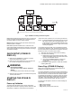
S7999B, S7999C SOLA LOCAL OPERATOR INTERFACE HOME PAGE 1234 SETUP PROGRAM MODULE KEY CLEAN SCREEN BUTTON FLOW BACK ICON FLOW HOME ICON ALWAYS TAKES YOU TO THE HOME PAGE SYSTEM CONFIG. SUMMARY PAGE ADVANCED SETUP CONFIGURE Configuration Groups Login Logout OPERATION DIAGNOSTICS DETAILS HISTORY CH Diagn. Test History OK Login Burner Control Alerts Lockouts Diagn. Alerts Analysis Silence DHW Digital I/O MODULATION SETPOINTS PUMPS ? Verify Analog I/O M13965 Fig. 8.
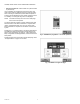
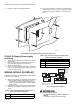
S7999B, S7999C SOLA LOCAL OPERATOR INTERFACE 4. Drill 3/16 in. holes for mounting the display. 5. Secure the OI Display to the panel using the four #6-32 screws and nuts, as shown in Fig. 10. (Standoffs are provided for mounting the OI Display from the back of the door.) CUTOUT OPTIONAL CUTOUT SPACER (4) WALL M29868 Fig. 10. Mounting the S7999C OI Display behind the door panel. S7999C OI Display Power supply mounting. 1. 2. 3. 4. Table 2.
S7999B, S7999C SOLA LOCAL OPERATOR INTERFACE S7999C MID-LEVEL DISPLAY Y 120 VAC L2 N L1 L V-INFINITY FSC-S5-12U 2 DISPLAY CAN BE CONNECTED TO MB1 OR MB2; A, B, C AS LONG AS THE REMAINING MB TERMINAL IS USED FOR THE SLAVE COMMUNICATIONS. 3 WIRE V-INFINITY POWER SUPPLY TO + AND - TERMINALS. 4 S7999C CONNECTED TO THE MASTER CAN CONFIGURE THE MASTER.
S7999B, S7999C SOLA LOCAL OPERATOR INTERFACE STARTING THE S7999C OI DISPLAY The “COM” LED exists for I/O traffic. 1. 2. Power-up Validation The Home page will appear and the “Power” LED will be on continuously and the “COM” LED will be blinking when the device is properly powered and communicating to the Sola Control. Make sure the LED is blinking. If the LED is not blinking: a. Make sure the proper connections have been made between the display and the Sola Control. b.
S7999B, S7999C SOLA LOCAL OPERATOR INTERFACE • History: used to view burner control history (see “History Button” on page 16 for more details). • ?: used to expand the pump status information. • Modulation: used to toggle between status displays: pump, setpoints, and modulation. Fig. 15. Configuration menu page. Shown is the S7999C on a Hydronic Control. No specific order for configuration is required. All parameters are enabled for editing, though some may not be applicable (e.g.
S7999B, S7999C SOLA LOCAL OPERATOR INTERFACE The user is not required to enter a configuration password for a parameter that has a lower access level than the access level achieved by an earlier password entry for any configuration group (as long as the user stays in the configuration pages). The user only needs to enter a password once until a parameter that has a higher access level is selected. Three levels of access to Sola Control parameters are permitted.
S7999B, S7999C SOLA LOCAL OPERATOR INTERFACE Change Parameter Settings Like operating parameters, safety parameters can be viewed without the need to enter a password. Change parameter settings by selecting the parameter on the page. A dialog box displays for the parameter with controls allowing the user to change the value (see Fig. 19). After changing the setting to a new value, press the OK button. Pressing the Cancel button leaves the parameter unchanged.
S7999B, S7999C SOLA LOCAL OPERATOR INTERFACE Safety lockouts are indicated on each configuration page as an alarm bell symbol. At the home (for S7999C) or status page (for S7999B), the History button turns red. If the S7999B is displaying the system status icons, the control in alarm will turn red. The lockout history can be displayed by pressing on the History button. The state information about each lockout is displayed along with the date/time that the lockout occurred (see Table 3).
S7999B, S7999C SOLA LOCAL OPERATOR INTERFACE of history to view. The user can also silence an audible alarm generated by the control during a lockout or alert by alarm condition. The date and time that each fault occurred is displayed in the lockout history. The lockout timestamp displays in both the lockout summary and detail information. This History dialog box provides an exploded view of the status information displayed in the History button (the font is larger).
S7999B, S7999C SOLA LOCAL OPERATOR INTERFACE Fig. 27. Control expanded lockout detail. Fig. 29. Hydronic operation page shown. Fig. 28. Control expanded alert detail. Fig. 30. Programmable annunciation. Operation Button The operation button displays the SOLA Control running operation, including setpoint and firing rate values.
S7999B, S7999C SOLA LOCAL OPERATOR INTERFACE Diagnostics Button System Configuration (S7999B OI DisplayOnly) The Diagnostics button displays analog and digital I/O status of the SOLA Control. A snapshot of the diagnostic status is displayed and updated once per second as it changes in the control. See “R7910A or R7911 Diagnostics” on page 44 for more information about this status. The OI Display has some functions related to general configuration for the control in the end user installation.
S7999B, S7999C SOLA LOCAL OPERATOR INTERFACE Table 5. Functional Configuration Groups. A new control is visible when configuration and status data is gathered from it. This collection procedure takes a few minutes. The control is marked as “Unknown” when no configuration information exists. Normally, control configuration data collection only needs to be performed when the control is initially installed. However, a re synchronization is necessary after the OI Display is reset. See Fig. 36.
S7999B, S7999C SOLA LOCAL OPERATOR INTERFACE Central Heat Parameters (R7910A Hydronic Control Only) Table 8 displays Central Heat Hydronic Control configuration parameters. Fig. 37. System identification and access configuration. (Hydronic Screen Shown.) Table 6 displays System Identification and Access parameters. Fig. 38. Central Heat hydronic configuration. Table 6. System Identification and Access Parameters.
S7999B, S7999C SOLA LOCAL OPERATOR INTERFACE Table 8. Central Heat Hydronic Configuration Parameters. (Continued) Parameter Table 9. Steam Configuration Parameters Parameter Comment Comment Modulation Rate Sensor Local Steam pressure on hysteresis P-gain Gain applied for the P portion of the PID equation 0-400 Differential from setpoint when boiler is turned on.
S7999B, S7999C SOLA LOCAL OPERATOR INTERFACE Domestic Hot Water (DHW) Configuration Parameters (R7910A Hydronic Control Only) Table 11. Domestic Hot Water (DHW) Configuration Parameters. (Continued) Table 11 displays Domestic Hot Water (DHW) configuration parameters.
S7999B, S7999C SOLA LOCAL OPERATOR INTERFACE Table 13. DHW Plate Heat Exchanger Configuration Parameters. (Continued) Parameter Table 14. Warm Weather Setpoint Configuration Parameters.
S7999B, S7999C SOLA LOCAL OPERATOR INTERFACE Modulation Configuration Parameters Steam Modulation Configuration Parameters Table 15 displays R7910A Hydronic Control Modulation configuration parameters. Table 16 displays R7911 Steam Modulation Configuration parameters. Fig. 43. Modulation configuration. Fig. 44. Steam modulation configuration. Table 15. R7910A Hydronic Control Modulation Configuration Parameters. Table 16. R7911 Steam Modulation Configuration Parameters.
S7999B, S7999C SOLA LOCAL OPERATOR INTERFACE Pump Configuration Parameters NOTE: The R7911 Steam Control does not have pumps, but the outputs are available to operate air dampers or accessories. CH Pump, Boiler Pump and System Pump are used for these output options. Table 17 displays Pump configuration parameters. Use the left and right arrows to switch between Central Heat, Boiler, DHW, System, Auxiliary 1, and Auxiliary 2 pumps. The parameters are the same for all pumps. Table 17a.
S7999B, S7999C SOLA LOCAL OPERATOR INTERFACE Statistics Configuration Parameters High Limit Configuration Parameters (R7910A Hydronic Control Only) Table 15 displays Statistics configuration parameters. Table 19 displays outlet high limit configuration parameters. Fig. 46. Statistics configuration. Fig. 47. High Limits configuration. Table 18. Statistics Configuration Parameters. Parameter Comment Table 19. High Limit Configuration Parameters.
S7999B, S7999C SOLA LOCAL OPERATOR INTERFACE Stack Limit Configuration Parameters Delta T Limit Configuration Parameters (R7910A Hydronic Control Only) Table 20 displays stack limit configuration parameters. Table 21 displays other limit parameters. Use the left and right arrows to switch between Inlet to Outlet Flow and Exchanger to Outlet Flow. The parameters are the same for all pumps. Fig. 48. Stack Limit configuration. Table 20. Stack Limit Configuration Parameters.
S7999B, S7999C SOLA LOCAL OPERATOR INTERFACE T-Rise Limit Configuration Parameters Anti-Condensation Configuration Parameters (R7910A Hydronic Control Only) Table 22 displays T-Rise limit parameters. Table 24 displays anti-condensation parameters. Use the left and right arrows to switch between Central Heat, Domestic Hot Water, Frost Protection, and Priority parameters. Table 22. T-Rise Limit Configuration Parameters.
S7999B, S7999C SOLA LOCAL OPERATOR INTERFACE Frost Protection Parameters (R7910A Hydronic Control Only) Annunciation Configuration Parameters Table 25 displays frost protection parameters. Table 26 displays annunciation configuration parameters. Fig. 51. Frost Protection configuration. Fig. 52. Annunciation configuration example. Table 25. Frost Protection Configuration Parameters. Table 26. Annunciation Configuration Parameters.
S7999B, S7999C SOLA LOCAL OPERATOR INTERFACE Fig. 53. Burner Control Interlocks control. Fig. 54. Burner Control Timings and Rates configuration. Table 27. Burner Control Interlocks Configuration. Table 28. Burner Control Timings and Rates Configuration.
S7999B, S7999C SOLA LOCAL OPERATOR INTERFACE Table 30. Burner Control Flame Failure Configuration. (Continued) Table 29. Burner Control Ignition Configuration.
S7999B, S7999C SOLA LOCAL OPERATOR INTERFACE After the first safety parameter group has been confirmed by the user (by pressing the Yes button), the next safety parameter group waits for verification as shown in Fig. 61. After successful login, the user presses the Begin button to start safety parameter verification. See Fig. 59. Fig. 59. Begin safety verification. Fig. 61. Safety parameter settings confirmed; next group waiting for confirmation.
S7999B, S7999C SOLA LOCAL OPERATOR INTERFACE If for some reason the user does not press the Reset button on the control within 30 seconds, the configuration is cancelled, as shown in Fig. 65. Fig. 63. Reset R7910A or R7911. When the user has pressed the Reset button on the control, completing verification procedure, a Verification Complete screen is displayed, as shown in as shown in Fig. 64. Fig. 65. Control reset timed out. Fig. 64. Safety parameter configuration complete.
S7999B, S7999C SOLA LOCAL OPERATOR INTERFACE Individual R7910A or R7911 Configuration Parameters Table 32. R7911 System Configuration Parameters. (Continued) Parameter Table 31 and Table 32 displays system configuration parameters for individual controls.
S7999B, S7999C SOLA LOCAL OPERATOR INTERFACE Lead Lag Slave Configuration Parameters (Hydronic Control Only) Use the left and right arrows to switch between Modulation, CH, DHW, Frost Protection, Warm Weather Shutdown, Algorithms, Rate Allocation, Add stage and Drop stage parameters. Table 34 displays Lead Lag Slave Configuration parameters. Fig. 68. Lead Lag slave configuration. Fig. 69. Lead Lag master configuration and Advanced Settings button. Table 34. Lead Lag Slave Configuration Parameters.
S7999B, S7999C SOLA LOCAL OPERATOR INTERFACE Table 37. Lead Lag Master Configuration Advanced Settings: Central Heat Parameters. Parameter Demand switch Setpoint source Table 41. Lead Lag Master Configuration Advanced Settings: Algorithms Parameters.
S7999B, S7999C SOLA LOCAL OPERATOR INTERFACE DETAILS R7910A or R7911 Status Data in Tables 45–Table 56 are displayed on the R7910A Hydronic or R7911 Steam status pages. A complete list of Status tables can be found in Table 60 on page 53. Details of the hydronic or steam system is accomplished through the detail status pages. The detail status page is shown below. The CH status data shown in Table 45 displays first when the CH Hydronic heating loop is selected on the Home page.
S7999B, S7999C SOLA LOCAL OPERATOR INTERFACE Table 46. DHW Hydronic Status.
S7999B, S7999C SOLA LOCAL OPERATOR INTERFACE Table 47. Burner Control Status. (Continued) Data Comment Firing rate % or RPM. Adjustable when firing rate control set to Manual.
S7999B, S7999C SOLA LOCAL OPERATOR INTERFACE Hydronic Demand and Modulation Status Table 49 displays the status page data for R7910A. Table 48. Hydronic Demand and Modulation Status. Data Comment Demand source CH, DHW, Lead Lag, or Frost Protection (parameter that has current priority) Firing rate % or RPM. Adjustable when firing rate control set to Manual. Demand rate % or RPM.
S7999B, S7999C SOLA LOCAL OPERATOR INTERFACE Table 50. Control Fan Status. Data Comment Fan speed % or RPM (current fan speed) Maximum fan speed Setpoint of maximum fan speed (% or RPM) Minimum fan speed Setpoint of minimum fan speed (% or RPM) The bar graph displayed for this status is the fan speed. Fig. 84. Hydronic CH pump status menu. Flame Detection Status The status data shown in Table 52 is displayed for flame detection in the R7910A or R7911. Table 52. Flame Detection Status. Data Fig.
S7999B, S7999C SOLA LOCAL OPERATOR INTERFACE Statistics Status Stack Limit Status Table 53 displays the statistics status page data for the R7910A or R7911. Though the Steam control will not have a pump, the output can be used to run some other auxiliary equipment. Table 54 shows the status page data for the control Stack Limit. Table 54. Stack Limit Status. Data Table 53. Control Statistics Status.
S7999B, S7999C SOLA LOCAL OPERATOR INTERFACE Fig. 89. Lead Lag Slave Status menu. Fig. 90. Lead Lag Master Status menu. Lead Lag Master Status - Hydronic Only R7910A OR R7911 DIAGNOSTICS Table 56 shows the status page data for Lead Lag Master. The diagnostic page displays analog and digital I/O status of the control. The digital I/O data is displayed as LEDs that are either on (green) or off (red) (see Fig. 91–93).
S7999B, S7999C SOLA LOCAL OPERATOR INTERFACE Table 57. Control Digital I/O Data. Data Fig. 92. Diagnostic digital I/O page (center).
S7999B, S7999C SOLA LOCAL OPERATOR INTERFACE INSTALLER CHECKOUT Diagnostics Tests Pressing the Diagnostics Test button launches the diagnostic tests. The first test displayed on the right side of the screen is the last selected test shown, as seen in Fig. 97. This screen enables the user to perform the following tests: Modulation Test: enables the user to verify that the burner is firing at the correct rate. (See Fig. 97.) Pilot Test: enables the user to verify that the pilot valve is functioning properly.
S7999B, S7999C SOLA LOCAL OPERATOR INTERFACE If Contrast or Volume are changed, Fig. 101 displays to allow saving these changes. Fig. 99. Pump test. S7999B OR S7999C DISPLAY SETUP AND DIAGNOSTICS Fig. 101. Setup settings changed. Cleaning the Screen When the user wants to clean the touch screen, the CLEAN SCREEN button is selected to freeze touch input temporarily for 30 seconds to allow the user to clean the screen. (See Fig. 102.
S7999B, S7999C SOLA LOCAL OPERATOR INTERFACE Fig. 105. Ethernet settings. Fig. 103. Screen disabled for cleaning. A Honeywell software server connectivity check can be performed by selecting the Check button. This button is only enabled when the Ethernet interface is enabled and active. The connectivity check tries for 15 seconds to connect to the Honeywell software server. Successful connection displays a “CONNECTED” message on the screen. An unsuccessful attempt displays “NOT CONNECTED.
S7999B, S7999C SOLA LOCAL OPERATOR INTERFACE The status variable with the largest range (minimum to maximum) is used as the Y-axis range in the graph. The S7999B must be assigned an IP address by a DHCP server for it to operate on the local network, so the Use DHCP box should be checked. However, because the S7999B requires this feature, it ignores the checkbox and always regards it as checked. The checkbox is included for future purposes when dynamic IP addressing isn’t required.
S7999B, S7999C SOLA LOCAL OPERATOR INTERFACE the graph so the Y axis depicts different degrees of detail for the data range. The viewing window can be moved up and down the graph to see the complete range when zoomed in. The smallest measurement interval is a single whole digit (no fractional precision) when the entire range exceeds 10 units, e.g., 20–30 degrees. Pressing the Stop button will pause trend data updates of the graph. The graph “freezes” the view when stopped.
• • • • Table 59. R7910/R7911 Trend Analysis Data. (Continued) Setpoint (for corresponding demand source) Burner firing rate Hysteresis on (for corresponding demand source) Hysteresis off (for corresponding demand source) Data Comment Stack temperature If enabled The Clear button is disabled for the PID analysis (doesn’t apply to hysteresis).
S7999B, S7999C SOLA LOCAL OPERATOR INTERFACE The Display clock is set by selecting the Date and Time button on the Advanced Setup page. A screen similar to the following figure (Fig. 114) displays. NOTE: It’s important that the time be set in the Display so correct timestamps are given to the R7910A or R7911 lockouts. The display’s time and date need to be set should power be interrupted to the display. Fig. 116. Code Version—bottom view.
Fig. 118. COM1 tab. S7999B Only COM2 is a Modbus gateway for Building Automation System (BAS) networking. Fig. 120. Processor Reset. When the Display is reset, the display will reboot and automatically seek out the Modbus™ device connected to it. When the search is complete, the display will return to the home page. Press the COM2 tab (see Fig. 119) to define settings: • Enable Modbus Gateway: This box must be selected to enable the COM2 BAS interface.
S7999B, S7999C SOLA LOCAL OPERATOR INTERFACE Table 61. Configurable Parameters. (Continued) Table 61. Configurable Parameters.
Table 61. Configurable Parameters. (Continued) Parameter Comment Table Page # # DHW enable Disable or Enable Domestic Hot 11 Water Loop DHW demand switch Table 61. Configurable Parameters.
S7999B, S7999C SOLA LOCAL OPERATOR INTERFACE Table 61. Configurable Parameters. (Continued) Table 61. Configurable Parameters.
S7999B, S7999C SOLA LOCAL OPERATOR INTERFACE Table 61. Configurable Parameters. (Continued) Table 61. Configurable Parameters.
S7999B, S7999C SOLA LOCAL OPERATOR INTERFACE Table 61. Configurable Parameters. (Continued) Parameter Comment CH frost protection enable Enabled Disabled DHW frost protection enable Enabled Disabled Lead Lag frost protection enable Enabled Disabled Table 61. Configurable Parameters.
S7999B, S7999C SOLA LOCAL OPERATOR INTERFACE Table 61. Configurable Parameters. (Continued) Parameter Comment Pilot test hold On Off Table 61. Configurable Parameters.
S7999B, S7999C SOLA LOCAL OPERATOR INTERFACE Table 61. Configurable Parameters. (Continued) Parameter Comment Absolute RPM maximum fan speed Table 61. Configurable Parameters.
S7999B, S7999C SOLA LOCAL OPERATOR INTERFACE Table 61. Configurable Parameters. (Continued) Table 61. Configurable Parameters.
S7999B, S7999C SOLA LOCAL OPERATOR INTERFACE 65-0303—05 62
.330 (8) 3.50 (89) .205 (5) 5.40 (137) 8.93 (227) 5.45 (138) M28852 Fig. 121. S7999C front-mount template.
S7999B, S7999C SOLA LOCAL OPERATOR INTERFACE 65-0303—05 64
M28851 Fig. 122. S7999C rear-mount template. 65 65-0303—05 4.30 (109) 5.45 (138) 8.93 (227) 1.50 (38) .92 (23) .75 (19) 5° .330 (8) 3.50 (89) .
S7999B, S7999C SOLA LOCAL OPERATOR INTERFACE 65-0303—05 66
S7999B, S7999C SOLA LOCAL OPERATOR INTERFACE 67 65-0303—05
S7999B, S7999C SOLA LOCAL OPERATOR INTERFACE Automation and Control Solutions Honeywell International Inc. 1985 Douglas Drive North Golden Valley, MN 55422 Honeywell Limited-Honeywell Limitée 35 Dynamic Drive Toronto, Ontario M1V 4Z9 customer.honeywell.com ® U.S. Registered Trademark © 2010 Honeywell International Inc. 65-0303—05 M.S. Rev. 04-10 Printed in U.S.A.