
Boiler User Manual


S7999B, S7999C SOLA LOCAL OPERATOR INTERFACE
65-0303—05 40
Fig. 76. DHW Hydronic Status menu (middle).
Fig. 77. DHW Hydronic Status menu (bottom).
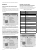
Burner Control Status
The Burner Control status page will display the status data
shown in Table 47.
The bar graph displayed for this status is the outlet sensor
temperature.
Fig. 78. Burner Control Status menu (top).
Fig. 79. Burner Control Status menu (bottom).
Burner control can be turned on and off in the R7910A or
R7911 by the user.
Table 47. Burner Control Status.
Data Comment
Alarm reason Description for alarm being on (maybe
lockout or a hold message)
Annunciator first out First annunciator input related to
lockout
Annunciator hold First annunciator input related to hold
Burner state Disabled, Locked out, Anti-short cycle,
Unconfigured safety data, Standby
Hold, Standby, Delay, Normal
Standby, Preparing, Firing, Postpurge
Sequence time Running time for timed burner control
operation (seconds)
Delay time Running display of delay time when
burner control in delay state.
Firing rate % or RPM. Adjustable when firing rate
control set to Manual.
Firing rate control Auto or Manual
Flame signal Flame signal strength
Hold code Description of hold message if locked
out
Lockout Description of lockout message if
locked out
Pilot test hold Off or Hold
Remote STAT On or Off
Note: Steam will show Steam psi as the bar graph
Table 47. Burner Control Status. (Continued)
Data Comment