
Install Instructions


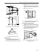

Table Of Contents

LP914A and LP915A
Pneumatic Temperature Sensors
INSTALLATION INSTRUCTIONS
DESCRIPTION
The LP914A and LP915A Pneumatic Temperature Sensors
are used with the RP908 or RP920 controllers to provide
proportional control of pneumatic valve or damper actuators.
CAUTION
Equipment Damage Hazard.
• Do not remove the cover of the sensor or tamper
with the sensor.
• Be careful not to dent or damage the sensor.
• Do not mount the LP914A or LP915A Pneumatic
Temperature Sensor on surfaces that overlap.
INSTALLATION
LP914A Rod and Tube
Duct Mount
Two no. 10 sheet metal screws and a gasket are furnished to
mount the LP914A in the duct. See Fig. 1 and 2. The sensing
element needs a 1 in. (25mm) hole.
GASKET 315182
M18351
Fig. 1. LP914A duct mounted.
® U.S. Registered Trademark
Copyright © 2002 Honeywell • All Rights Reserved
2-1/2 (64)
7 or 15
(178 or 381)
2
(51)
1
(25)
11/32
(9)
2-29/32
(74)
M18352
Fig. 2. LP914A dimensions in In. (mm).
Through Wall Mount
The master version of the LP914A can be mounted in any wall
up to 12 in. (305mm) thick. See Fig. 3 and 4.
1. Prepare a 5/8 in. (16mm) hole for the sensing element.
2. Insert the sensing element.
3. Attach the sun shade from the opposite side of the wall.
4. Use the small set screw to fix the position of the sensing
element through the wall.
5. Check the sun shade position and tighten the set screw
on the mounting bracket.
NOTE: The sensor mounting bracket has two 1/4 in. (6mm)
holes for fastening to the wall. When the wall in thin,
the head of the sensor can protrude slightly into the
room.
2-1/2
1/2 (13) DIA.
(64)
7/16
(11)
1-1/2
(38)
1/4 (6) DIA.
3 (76)
M18353
Fig. 3. LP914A wall model mounting bracket.
95-5527E
F