
Install Instructions
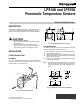


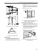

Table Of Contents

LP914A AND LP915A PNEUMATIC TEMPERATURE SENSORS
M18358
Fig. 4. LP914A wall mounted.
Well Mount (Water Model)
A bracket, two speed nuts and two no. 10-24 screws are
furnished for mounting a water model. See Fig. 5.
1. Loosen the screws of the mounting bracket.
2. Remove one screw completely and swivel the bracket
to the side.
3. Put the sensing element into the well, which has been
factory filled with heat conductive compound.
NOTE: The compound is evenly distributed when the sens-
ing element is inserted.
4. When the sensor is fully into the well, swivel the bracket
back into position so that the lip fits under the nut head
of the well.
NOMINAL
DIMENSIONS
LP914 WELLS
SENSOR DIMENSIONS
WELL
IN IN. (MM)
MATERIAL
315046A
15-3/8 (390)
COPPER
315046B
7-3/8 (187)
COPPER
315904A
15-5/16 (389)
STAINLESS
315904B
STEEL
7-5/16 (186)
M18357
Fig. 5. LP914A well mounted.
INSTALLING LP914 INTO AN EXISTING LP902 WELL
1. Remove the LP902 from the well.
2. Add the 1/2 in. x 3/8 in. brass pipe bushing (part #1697).
3. Seal the well with heat conductive compound (part
#107408).
4. Mount the LP914A. See Fig. 6.
1/2 IN. X 3/8 IN. BRASS
PIPE BUSHING (NO. 1697)
WELL
BRACKET
LP914
M18354
Fig. 6. LP914A mounted in an existing LP902 well.
LP915A Liquid Filled
BEFORE INSTALLING
Mount the sensor element in an accessible location where
average temperatures can be sensed. See Fig. 7 and 8.
NOTE: When used as a discharge-air or mixed-air controller,
mount the element downstream from the heating coil
or mixing dampers to ensure reasonable mixing of
the air before the temperature is measured.
1. Use the three no. 10 sheet metal screws and gasket to
mount the LP915A.
2. Use the 314439 capillary clips (order separately) to
install an averaging element. See Fig. 9.
GASKET
CAPILLARY
#10 MOUNTING
SCREWS (3)
M18359
Fig. 7. LP915A duct mounted.
95-5527EF 2