
Install Instructions
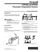
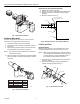
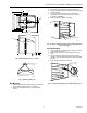

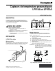
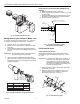
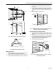

Table Of Contents

3-5/8
LP914A AND LP915A PNEUMATIC TEMPERATURE SENSORS
13/64 (5)
2-1/2
(64)
3 (76)
13/64
(5)
(92)
3
(76)
3-15/16 (90)
3-1/4 (82)
1/8 NPT
2-21/32
(67)
7/32 (6)
7/8
(22)
M18360
Fig. 8. LP915A dimensions in in. (mm).
CLEARANCE FOR
#10 SCREW
TAB CAN BE BENT ALONG DOTTED LINE
TO FACILITATE MOUNTING.
M18355
Fig. 9. 314439 capillary clip.
Duct Mounting
1. Use the template provided and drill a large center hole
for the sensing element to pass into the duct.
2. Drill three mounting holes for no. 10 sheet metal
screws.
3. Run the sensing element into the duct. See Fig. 10.
4. Fasten the device to the duct with the three sheet metal
screws provided.
5. Form the element in the duct so that air samples
throughout the duct are sensed. See Fig. 5 and 6 for
typical duct installations.
6. Firmly support the element in the duct.
WIRE FASTENING
ELEMENT
M18356
Fig. 10. Sensor element mounted in duct using perforated
strap iron support.
Alternate Mounting
1. Locate positions for capillary clips on sides of duct and
mark for drilling. See Fig. 11.
2. Drill holes for use of no. 10 sheet metal screws. See
Fig. 6.
3. Place the element inside the duct and loop over the
capillary clips to provide samples of air from throughout
the duct.
4. Firmly support the element in the duct.
Fig. 11. Alternate mounting using 314439 capillary clip.
USE NO. 10 SHEET
METAL SCREWS
BEND HERE
IF NECESSARY
M18361
3 95-5527EF