
Install Instructions

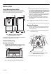
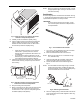
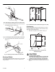
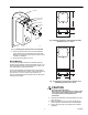


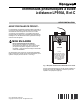

Table Of Contents

SENSING
BULB
CAPILLARY
THERMOSTAT
SCALEPLATE
CONTROL SHAFT
MAIN
SETPOINT
KNOB
10-32 x 1/4-IN.
SCREW (2)
BRANCH
PROTECTED BARBS
C4652
Fig. 14. Installing the setpoint knob and scale plate.
3. Place the setpoint knob on the control shaft with the
pointer aligned over the mid-mark on the scale plate.
See Fig. 14. Secure the knob firmly with the set screw to
maintain the calibration.
4. Mount the sensing bulb in the unit.
Bracket Mounting
The LP916 mounting kit model uses a 316016A or B bag
assembly when installed in terminal units similar to Fig. 5 or 6.
These assemblies include a mounting bracket, screws, nuts,
clips, bulb hangers, scale plate and knob.
The two bag assemblies are similar except for the length of
the mounting bracket and the centers of the bracket mounting
holes. See Fig. 15 and 16. The two sets of holes in the
mounting brackets allow the thermostat to be mounted either
vertically or horizontally.
3-1/4
(83)
5/8
(16)
1-7/8 (48)
2-3/4 (70)
C4648
Fig. 15. Mounting bracket in 316016A bag assembly.
Dimensions are in in. (mm).
5-5/16
(135)
5/8
(16)
2 (51)
2-3/4 (70)
C4649
Fig. 16. Dimensions of the mounting bracket in the
316016B bag assembly in in. (mm).
CAUTION
Equipment Damage Hazard.
Be careful not to change position of control shaft
when removing the shipping stop and attaching
the setpoint knob and scale plate to the
thermostat.
1. Assemble the thermostat, mounting bracket and scale
plate. See Fig. 17.
2. Place the setpoint knob on the control shaft with the
pointer aligned over the mid-mark on the scale plate.
3. Secure the knob firmly with the setscrew to maintain
calibration.
5 95-5559EF