
Install Instructions

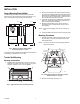
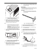
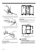


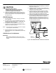

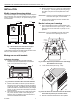
Table Of Contents

CAPILLARY
BE SURE THIS TUBE IS UNDER
BULB HOLDER, AS SHOWN
M18343
Fig. 9. Mounting the capillary tubing in the bulb holder.
6. Insert the bulb and bulb holder into the duct through the
hole prepared in Step 1. See Fig. 10.
Fig. 10. Inserting the bulb and bulb holder into the duct.
7. Use screws to fasten the bulb holder to the duct wall.
See Fig. 11.
DUCT
BULB
HOLDER
SCREW
HOLES IN
DUCT WALL
CONTROLLED
AREA
BULB
M18344
M18345
Fig. 11. Fastening the bulb holder to the duct wall.
Mounting Kit Model
The LP916 mounting kit model is shown in Fig. 12. This model
can be either panel mounted or mounted in a terminal unit
using a bracket.
BM
+
+
+
+
+
+
+
4-1/2
(115)
4-7/8
(124)
2-1/16 (53)
C4653
2-3/16 (56)
Fig. 12. Dimensions of the LP916 mounting kit in in. (mm).
Panel Mounting
Mounting the LP916 mounting kit model directly on a panel
requires a 306016C bag assembly. The kit includes a scale
plate, knob and mounting screws.
1. Drill holes in the panel on the centers. See Fig. 13.
C4650
3/8 (10) DIA
7/32 (6) DIA -2
PANEL
2-1/4
(57)
1-1/8
(29)
Fig. 13. Hole dimensions in in. (mm) for the
LP916 mounting kit.
CAUTION
Equipment Damage Hazard.
Be careful not to change position of control shaft
when removing shipping stop and attaching the
setpoint knob and scale plate to the thermostat.
2. Mount the thermostat from the rear of the panel and
secure on the front with the scale plate and screws. See
Fig. 14.
95-5559EF 4