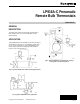
LP916A-C Pneumatic Remote Bulb Thermostats SERVICE DATA GENERAL DESCRIPTION The LP916 Thermostats are bleed-type controllers with a fixed throttling range. They have a liquid-filled, remote thermal element. APPLICATION Typical applications for the LP916A are duct-mounted (Fig. 1) and mixed air control (Fig. 2). The LP916B is typically used for fan coil unit control (Fig. 3). Typical applications for the reverse acting LP916C are cooling coil control similar to Figure 1 or fan coil control (Fig. 4).
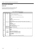
LP916A-C PNEUMATIC REMOTE BULB THERMOSTATS SPECIFICATIONS Models: LP916A: Direct Acting. LP916B: Reverse acting at 9 or 13 psi (62 or 90 kPa) supply pressure (Summer), direct acting at 18 psi (124 kPa) supply pressure (Winter). LP916C: Reverse Acting. Maximum Safe Air Pressure: 25 psi (172 kPa). Maximum Safe Temperature: Duct-mounted models 190F (88C); all others 135F (57C). Nominal Main-Line Pressure: LP916A & C: 18 psi (124 kPa). LP916B: 18 psi (124 kPa) heating, 9 or 13 psi (62 or 90 kPa) Cooling.
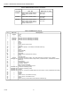
LP916A-C PNEUMATIC REMOTE BULB THERMOSTATS Table 1. LP916 Specifications. Model Setpoint Range F/C Throttling Range F/C Restrication Size In. Bulb Size Inches Mounting Bracket LP916A1001 LP916A1019 1 65-85F 65-85F or 19-30C 3.5F 3.5F or 2C 0.007 0.007 3/8 x 9 1/2 x 5 Separate Integral LP916A1027 1 65-85F 3.5F 0.007 3/8 x 9 Integral LP916A1035 1 55-95F 7.0F 0.007 3/8 x 6-11/16 Integral LP916A1050 1 17-27C 1.95C 0.007 1/2 x 5 Integral LP916A1068 1 17-27C 1.95C 0.
LP916A-C PNEUMATIC REMOTE BULB THERMOSTATS OPERATION CLEANING LP916A (Direct Acting) Remove cover. Use cleaning solvent to clean all surfaces. Clean the element and capillary tubing, making certain neither is damaged or kinked. Do not bend the capillary tubing in a short radius. When temperature at the sensing element falls below setpoint of the LP916A, branchline pressure to the normally open (n.o.) valve is lowered, and the valve is modulated open to maintain setpoint temperature.
LP916A-C PNEUMATIC REMOTE BULB THERMOSTATS CALIBRATION CHECK Set setpoint knob to temperature measured at bulb location. Branchline pressure should be 8 ±1 psi (55 ±7 kPa). CALIBRATION LP916A & C A Apply 18 psi (124 kPa) main-line pressure. B Measure temperature at sensing bulb location. C Remove setpoint knob using 5/64-in hex wrench to loosen setscrew. D Rotate setpoint shaft to achieve 8 psi (55 kPa) branchline pressure. Allow enough time for pressure build-up.
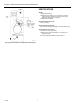
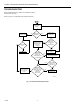
LP916A-C PNEUMATIC REMOTE BULB THERMOSTATS TROUBLESHOOTING Before troubleshooting the LP916, check branchline piping and actuators for leaks. Refer to Figure 7 to troubleshoot the LP916 Thermostat.
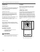
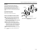
LP916A-C PNEUMATIC REMOTE BULB THERMOSTATS REPAIR The only repair recommended for the LP916 is the replacement of the plate and tube assembly, gaskets, restriction plate, and filters with connector assembly and gasket. Since February 1984, models have a different connector assembly with a single gasket, these are included in Repair Kit 14003113-002, as shown in Figure 8. All available parts are listed in the PARTS AND ACCESSORIES section.
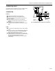
LP916A-C PNEUMATIC REMOTE BULB THERMOSTATS PARTS AND ACCESSORIES PARTS LIST See Figure 9 for LP916A &C exploded view and Figure 10 for LP916B exploded view. See Tables 2 and 3 for LP916A &C parts list and Tables 3 and 4 for LP916B parts list. Table 2. LP916A and C Parts list (Fig. 9). Key 1 2 3 4 5 6 7 8 9 10 11 12 13 14 15 16 17 18 19 20 21 22 23 24 25 26 27 28 29 75-5559 Part No.
LP916A-C PNEUMATIC REMOTE BULB THERMOSTATS S22649 Fig. 9. LP916A and C Exploded view (See Tables 2 and 3).
LP916A-C PNEUMATIC REMOTE BULB THERMOSTATS Table 3. LP916A-C Element and lever assemblies. Assembly Part No. Part No. Bulb Size in. (mm) 316372A A1001, A1027, A1068, B1009, B1025, B1041, B1066, C1007, C1023 3/8 x 9-1/2 (9.5 x 241) 316372B A1019, B1017, B1058, C1049 1/2 x 5-3/4 (13 x 146) 316372Ç A1035, A1076, A1118, A1126, A1134, A1142, A1159, A1175, B1074, B1082, B1090, B1108, C1080, C1098, C1114 3/8 x 6-3/4 (10 x 172) Table 4. LP916B Parts list (Fig. 10). Key Part No.
LP916A-C PNEUMATIC REMOTE BULB THERMOSTATS S22649 Fig. 10. LP916B Exploded view.
LP916A-C PNEUMATIC REMOTE BULB THERMOSTATS ACCESSORIES A B C D Gage 305965 (0 to 30 psi). Gage Adaptor MQP729. Internal Mounting Bracket AK3993. Mounting Kits for fan coil units: 316016A with small bracket. 316016B with full length bracket. 316016C with scaleplate, knob, and mounting screws only. Home and Building Control Honeywell Inc. Honeywell Plaza P.O. Box 524 Minneapolis MN 55408-0524 75-5559 Rev. 6-87 Printed in U.S.A.