
Submittal Sheet
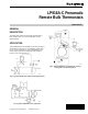


LP916A-C PNEUMATIC REMOTE BULB THERMOSTATS
5
75-5559
CALIBRATION CHECK
Set setpoint knob to temperature measured at bulb location.
Branchline pressure should be 8 ±1 psi (55 ±7 kPa).
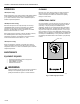
CALIBRATION
LP916A & C
A Apply 18 psi (124 kPa) main-line pressure.
B Measure temperature at sensing bulb location.
C Remove setpoint knob using 5/64-in hex wrench to
loosen setscrew.
D Rotate setpoint shaft to achieve 8 psi (55 kPa)
branchline pressure. Allow enough time for pressure
build-up.
E Replace the knob and position the pointer to
correspond to the temperature sensed by the remote
bulb.
LP916B
A For direct action, follow Steps 1 through 5 for LP916A
and C.
B For reverse action (except LP916B1058), apply 13 psi
(90 kPa) main-line pressure. For the LP916B1058,
apply 9 psi (62 kPa) main-line pressure.
C Adjust switchover lever stop (Fig. 6) to achieve 8 psi
(55 kPa) branchline pressure when the setpoint knob is
set to measured bulb temperature. For the
LP916B1058 model, branchline pressure should be
6 psi (41 kPa).
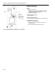
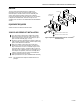
Fig. 6. LP916B Automatic switchover mechanism.
SWITCHER
LEVER STOP
SWITCHER
SPRING
ADJUSTING NUT
STUD
C8363