
Install Instructions


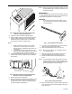


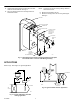


Table Of Contents

INSTALLATION
Integral Mounting Bracket Model
The LP916 integral mounting bracket model includes two
Tinnerman nuts, two sensing bulb hangers and two No. 10 x
5/8 in. sheet metal screws. See Fig. 2 for dimensions.
3/8 (10)
9/16 (14)
4-5/8
(117)
BM
O
O
L
E
A
R
M
E
N
R
M
A
L
O
C
R
H O N E Y W E L L
2-3/4 (70)
3 (77)
C4647
Fig. 2. Dimensions of the LP916 integral
mounting bracket in in. (mm).
The integral mounting bracket model allows the thermostat to
be mounted in a terminal unit or on a duct.
Terminal Unit Mounting
Mounting Considerations
1. Install the return air thermostat in one of the end com-
partments or pockets of the unit. See Fig. 3. Any of the
positions, points A, B, C or D, are acceptable.
C
D
M18340
Fig. 3. Typical terminal unit mounting locations.
A
B
E
2. Mount the thermostat in the location where the mount-
ing screws are readily accessible and the setpoint knob
easily reached. Preferably the scale is visible from the
top of unit through the access hatch or from the front of
the unit when the front panel is removed.
3. Locate air connections in accessible area. If necessary,
add 1/4-in. plastic elbow and/or tubing extensions to
barb connectors before installation.
4. Mount the bulb at either of the E points. See Fig. 3.
Avoid kinks, dents or sharp bends in the 36 in. (914
mm) capillary.
NOTE: Mount so that capillary does not rub on sharp cor-
ners.
5. Locate the plastic tubes away from the hot supply lines.
Mounting Procedures
1. Hold the thermostat in place and mark screw hole cen-
ters. See Fig. 4. Punch or drill the pilot holes for the
sheet metal screws.
NOTE: Tinnerman nuts can be used by making clearance
holes for the screws.
Fig. 4. Alternate locations for mounting screws.
Dimensions are in in. (mm).
2. Mount the thermostat. See Fig. 5 or 6.
M18341
MOUNTING
FLANGE
MOUNTING
FLANGE
2 ±1/4
(51±6)
2 ±1/4
(51±6)
2 ±1/4
(51±6)
95-5559EF 2