
Install Instructions


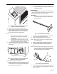


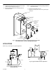


Table Of Contents

M18346
Fig. 5. Terminal unit top view with the thermostat
mounted in the preferred position.
3. Carefully uncoil and extend the capillary tubing.
4. Use the existing knockout and insert the sensing bulb
with the capillary through the hole. Locate the bulb
between the return air filter and the coil. Bush hole in
the unit wall to protect the capillary tubing.
NOTE:
√ When the existing knockout is not convenient,
make a 5/8-in. (16 mm) hole in the unit wall
between the end compartment, filter and the coil
compartment.
√ Do not locate the sensing bulb where it can be
affected by any outdoor airflow such as a unit that
uses a fixed-percentage outdoor air damper.
5. Clip the two bulb hangers to the drain pan or edge of the
frame member. See Fig. 6. Tap the top end to ensure
firm mounting.
SENSING ELEMENT
AND HANGERS
M18347
Fig. 6. Alternate mounting of the thermostat at the
bottom front of the end compartment.
6. Snap the sensing bulb into position.
7. Before connecting the air, leave main line disconnected
for about one minute to clear and dry the tubing. Air
connections are a 1/4-in. push-on sharp-barb type with
the labels M (Main) and B (Branch).
NOTE: When air connections are towards the back, connect
the appropriate lengths of tubing to the barb connec-
tors before mounting.
Duct Mounting
Duct mounting requires a 107324A duct bulb holder. See Fig.
7. The sensing bulb should be located in the duct where air of
representative temperature can freely circulate.
IMPORTANT
Do not mount the bulb close to hot pipes, cooling
coils and other places where the air temperature is
not representative.
C7866
Fig. 7. The 107324A duct bulb holder.
1. Cut a 3/4-in. (19 mm) diameter hole in the duct wall to
admit the sensing bulb and bulb holder.
2. Mount the thermostat near the hole in the duct.
NOTE: Mount on top of the duct or on a bracket or angle
iron, obtained locally.
3. Using the bulb holder as a template, mark and drill
holes for the bulb holder and mounting screws.
4. Shorten the bulb holder to the desired length. See
Fig. 8.
NOTE: The bulb holder should be long enough to hold the
sensing bulb in the freely circulating air away from
the duct wall. Neatly coil any excess capillary tubing
at the thermostat case or the bulb holder.
M18342
Fig. 8. Shortening the bulb holder.
5. Place the capillary tubing in the bulb holder channel and
pinch the top edges of the holder together at each seg-
ment. See Fig. 9.
3 95-5559EF