
Install Instructions
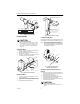
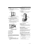
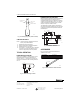
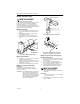
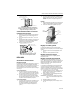
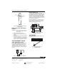
Table Of Contents

LP920A and B
Remote Bulb Controller
INSTALLATION INSTRUCTIONS
BEFORE INSTALLATION
CAUTION
Equipment Damage Hazard.
Use care in handling elements. A kinked capillary
renders the controller useless.
Whenever the capillary is bent, maintain a minimum
radius of 1 in. (25mm). Use a 1 to 3 in. (25 to 76mm)
pipe, a large screwdriver handle or a hammer handle to
achieve this radius.
Before connecting the air, blow main air from the line for
about one minute to clear and dry the line. Branch and
main barbs are clearly marked B and M. See Fig. 1. The
push on, sharp-barb connectors require no spring clips.
Fig. 1. Connector markings.
The controller is factory calibrated. It must be
recalibrated when the throttling range is changed from
factory settings.
Avoid hot supply lines with the plastic air piping. Refer to
Fig. 2 for the LP920 approximate dimensions.
INSTALLATION
Well-Mount Model
One bracket, two speed nuts and two no. 8 sheet metal
screws are furnished for securing the well-mounted
model. See Fig. 3.
1. Loosen the mounting bracket screws.
2. Remove one screw completely and swivel the
bracket to the side.
3. Put the sensing element into the well which is par-
tially filled with heat conductive compound (part no.
107408).
NOTE: The compound evenly distributes itself when
the sensing element is inserted.
4. Swivel the bracket back into position when the sen-
sor is fully into the well.
5. Secure so that the lip fits under the hex head of
the well.
6. Retighten the screws.
Fig. 2. LP920 approximate dimensions in in. (mm).
B M
3-1/8
(80)
2-11/16
(68)
2-3/4
(70)
5-9/16 (142)
2-1/4
(57)
M18367
® U.S. Registered Trademark
Copyright © 2002 Honeywell • All Rights Reserved
95-7273EF