
Install Instructions
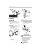

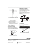
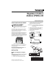
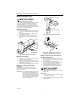
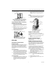
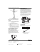
Table Of Contents

LP920A AND B REMOTE BULB CONTROLLER
WELL
315046B
315904B
(IN.)
7-3/8
7-5/16
MATERIAL
COPPER
STAINLESS STEEL
(MM)
187
186
NOMINAL DIMENSIONS LP920 WELLS
SENSOR DIMENSION
BRACKET
1/2 NPT
1 IN. HEX HEAD
M18368
Fig. 3. LP920 well-mounted model.
Duct Mount Models
CAUTION
Equipment Damage Hazard.
When locating duct-mounted models, consider
the maximum element safe temperature, 230°F
(110°C). Avoid contact with or radiation from
any high pressure steam or high temperature
water coils.
Integral Bulb Model
1. Drill, saw or punch 1 in. (25mm) diameter hole for
the sensing element. See Fig. 4.
2. Bend the element holder to the side for ducts of
less than 15 in. (380mm).
3. Use two no. 8 screws (not furnished) with a gasket
(furnished) to mount on the duct work.
GASKET
DUCT
1 IN. (25 MM)
DIAMETER
HOLE
BEND FOR DUCT OF
LESS THAN 15 IN. (380 MM)
CAUTION
MINIMUM 1 IN. (25 MM) RADIUS
M18369
NO. 8 SHEET
METAL SCREWS
Fig. 4. LP920 integral bulb model.
Remote Bulb Model
1. Use two no. 8 screws (not supplied) to mount in a
convenient location.
2. Insert the bulb into a 1 in. (25mm) hole in the duct
work as with the integral bulb installation. See Fig.
5.
3. Apply gasket (provided) to the duct.
LP920 MOUNTED TO COLUMN
WITH NO. 8 SCREWS
CAPILLARY
TO ELEMENT
ELEMENT LOCATED IN DUCT
APPROXIMATELY 10 FEET (3M) HIGH.
DUCT
M18370
CONTROLLER IN CONVENIENT
LOCATION APPROXIMATELY
5 FEET (1.5M) FROM FLOOR
Fig. 5. LP920 remote bulb model.
Averaging Element Model
Mount controller element in an accessible location where
it is distributed to sense average temperature. See Fig. 6.
NOTE: When used as a discharge air or mixed air con-
troller, mount the element far enough down-
stream from the heating coil or mixing dampers
to ensure reasonable mixing of the air before its
temperature is measured.
NO. 8
SHEET METAL
SCREWS (2)
GASKET
CAPILLARY
M18371
Fig. 6. LP920 averaging element
duct mounted controller.
Duct Mounting Using Perforated Strap Iron
Supports
1. Drill a large center hole for the sensing element to
pass into the duct and two mounting holes for no. 8
sheet metal screws. See Fig. 7.
2. Run the sensing element into the duct.
3. Fasten the device and gasket onto the duct with
two sheet metal screws (not provided).
4. Form the element in the duct for uniform sensing of
samples throughout the duct.
CAUTION
Equipment Damage Hazard.
Be careful not to crush the element when using
wire ties.
95-7273EF 2