
Install Instructions
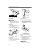

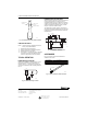
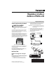
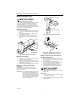
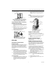
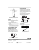
Table Of Contents

LP920A AND B REMOTE BULB CONTROLLER
IMPORTANT LP920B (REVERSE ACTING)
Remember to maintain the minimum 1 in.
(25mm) bend radius.
5. Support the element firmly in the duct. Fig. 7 shows
an installed element.
PERFORATED STRAP IRON
(PART NO. 2632)
WIRE FASTENING
ELEMENT
M18363
Fig. 7. Averaging element mounted in duct using
perforated strap iron support.
Alternate Mounting Using Capillary Clip
1. Locate positions for capillary clips on the sides of
duct and mark for drilling.
2. Drill holes for no. 10 sheet metal screws as shown
in Fig. 8.
3. Place the element inside the duct and loop over
capillary clips (no. 314439) to sense uniform sam-
ples of air from throughout the duct.
4. Firmly support the element on the duct.
USE NO. 10 SHEET
METAL SCREWS
BEND HERE
IF NECESSARY
CAPILLARY CLIP
NO. 314439
M18361
Fig. 8. Alternate mounting using
capillary clip no. 314439.
ADJUSTMENTS
Operational Check
Primary Controller
Verify device operation by checking the pressure at the
branch line tap (BLP) located below and to the left of the
cover holding screw. The BLP builds up and bleeds down
through its full range as the setpoint knob is rotated. See
Fig. 9.
LP920A (DIRECT ACTING)
1. Turn the setpoint knob to 150°F (66°C). The BLP
bleeds down to below 1 psi (7 kPa).
2. Turn the setpoint knob to 35°F (2°C). The BLP
builds up to within 1 psi (7 kPa) of the main line
pressure.
1. BLP builds to within 1 psi (7 kPa) of main line pres-
sure when setpoint knob is set at 150°F (66°C).
2. BLP bleeds below 1 psi (7 kPa) when setpoint
knob is set to 35°F (2°C).
Limit Controller
1. Set the primary controller to supply full MLP to the
limit controller.
2. Proceed as in the primary controller above.
BRANCH
LINE
TAP
COVER
PLATE
SCREW
SCALEPLATE
SCREWS (2)
M18362
Fig. 9. Branch line tap location.
Scaleplate Adjustment
The LP920 is shipped with a Fahrenheit scaleplate. For
Celsius conversion:
1. Remove the two scaleplate screws. See Fig. 9.
2. Turn the scaleplate over and replace the screws.
Setpoint Adjustment
Rotate the setpoint knob to the desired temperature.
Throttling Range Adjustment
The throttling range is factory set at 10°F (6°C) and does
not required readjustment for most applications.The
throttling range lever is accessible after removing the
front cover plate. See Fig. 10.
The lever and attached sliding indicator comprise the
throttling range adjustment mechanism. Graduation
marks from bottom to top (minimum to maximum)
translate as 5, 10, 15, 20 and 25°F (3, 6, 9, 12, and 15°C)
throttling ranges.
1. Remove the cover plate by loosening one screw
and sliding the cover so the keyhole clears the
screw head. See Fig. 9.
2. Move the sliding indicator to achieve the predeter-
mined throttling range.
NOTE: This is usually at the lowest point where rapid
cycling does not occur.
3. Replace the cover plate.
4. Check the setpoint calibration. See Fig. 10.
3 95-7273EF