
Submittal Sheet


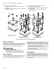

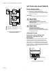
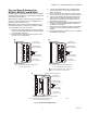
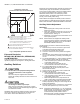
Table Of Contents

SERIES 71, 72, AND 76 MODUTROL IV™ MOTORS
63-2640—06 6
To mount the motor with the bracket:
1. Mount the bracket to the equipment with existing or stan-
dard bolts.
2. Using the provided bolts, mount the motor to the bracket
threaded holes. See Fig. 3.
For valve linkage applications (other than the Q5001):
1. Mount the bracket to the linkage.
2. Position the motor on the bracket to align the motor shaft
with the linkage.
3. Attach the motor to the bracket with the four bolts
provided. See Fig. 4.
Fig. 3. Mounting the motor with an adapter bracket.
Damper Linkages
The motor does not include a crank arm. Order the crank arm
separately (see Accessories in the Specifications section). For
detailed instructions on the assembly of specific linkages, refer
to the Installation Instructions packed with the linkage.
CAUTION
Equipment Damage Hazard.
Stalling a motor can damage the drive shaft.
Ensure installation of motors and linkages allows the
motor to drive through full stroke without obstruction.
Valve Linkages
The Q100 Linkage requires a 220738A Adapter Bracket for all
valve applications. Applications with the Q5001 Valve Linkage
do not require the 220738A Adapter Bracket (see Fig. 4).
For detailed instructions on specific linkage assemblies, refer
to the instruction sheet packed with the linkage. In general,
check the following points when installing a motor and linkage:
• Adjust valve and louver-type damper linkages so the damper
or valve moves through only the maximum required distance
while the motor moves through its full stroke.
• With modulating control, maximum damper opening should
be no more than 60 degrees. Little additional airflow is
provided beyond this point.
• Do not exceed load and torque ratings in any application.
Junction Box
When used with liquid-tight conduit connectors, the junction
box provides NEMA 3 weather protection for the motor. The
junction box, standard with replacement motors, encloses the
terminals and provides knockouts for wiring conduits. Housing
an internal transformer or internal auxiliary switches requires
using a junction box.
M18999
EQUIPMENT
BASE
ADAPTER
BRACKET
STANDARD
BOLTS (4)
MOTOR
BOLTS
PROVIDED (4)
WIRING
BOX
NON-SPRING RETURN
SPRING RETURN
1 #12 OR 1/4" ZINC PLATED
MACHINE SCREWS OR BOLTS
1
POWER
END
POWER END
POWER END