
Submittal Sheet

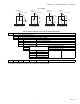
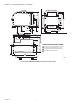
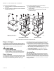
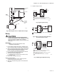
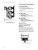
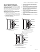
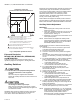
Table Of Contents

SERIES 71, 72, AND 76 MODUTROL IV™ MOTORS
9 63-2640—06
Zero and Span Adjustment for
M7284Q, M7285Q, and M7294Q
M7284Q, M7285Q, and M7294Q actuators have the capability
of adjustable zero and span. Fig. 10 shows the module with the
zero and span potentiometers.
Zero: Sets input voltage to define the 0% angle of rotation. It is
factory set to minimum position and can be adjusted to the
maximum position of 20mA or 10V.
Span: Adjusts motor response to travel a full stroke through
the selected input span. It is factory set to maximum position,
and is adjustable from 4-20mA or 2-10Vdc.
1. Adjust the start potentiometer fully clockwise (maximum
zero) and the span potentiometer fully counterclockwise
(minimum span). See Fig. 10.
2. Set the controller current to the value required to drive
the motor to the closed position.
3. Turn the start potentiometer slowly counterclockwise
until the motor begins to open. This is defined as the
start or zero setting.
4. Set the controller current to the value required to drive
the motor to the fully open position. The motor will open.
5. Turn the span potentiometer clockwise until the motor
starts to close. The difference between the fully open
span position current and the zero position current is
defined as the operating span.
6. Recheck the start and readjust the span potentiometer if
necessary. Turn the start potentiometer clockwise to
increase the zero position.
7. Recheck the span and readjust the span potentiometer if
necessary. Turn it clockwise to increase the full span
position.
8. For sequential operation, as shown in Fig. 11, repeat the
above steps for each motor.
Fig. 10. Terminals and adjustments.
RIGHT/INNER
AUXILIARY SWITCH
INNER AUXILIARY
SWITCH CAM (BLUE)
POWER
END
OUTER AUXILIARY
SWITCH CAM (RED)
LEFT/OUTER
AUXILIARY SWITCH
NOTE: FEATURES AVAILABLE ON SOME MODELS ONLY.
M13648A
(+)
(-)
T2
T1
F
RIGHT/INNER
AUXILIARY SWITCH
INNER AUXILIARY
SWITCH CAM (BLUE)
POWER
END
OUTER AUXILIARY
SWITCH CAM (RED)
LEFT/OUTER
AUXILIARY SWITCH
NOTE: FEATURES AVAILABLE ON SOME MODELS ONLY.
Y(+)
T2
T1
F (TEST)
A
B
V(-)
2 TO 10 VDC INPUT MOTORS 4 TO 20 mA NONADJUSTABLE INPUT MOTORS
NOTE: FEATURES AVAILABLE ON SOME MODELS ONLY.
4 TO 20 mA ADJUSTABLE INPUT MOTORS
C
SPAN ADJUST POTENTIOMETER
START ADJUST POTENTIOMETER
START ADJUST
MIN MAX
SPAN ADJUST
MIN MAX
RIGHT/INNER
AUXILIARY SWITCH
INNER AUXILIARY
SWITCH CAM (BLUE)
POWER
END
OUTER AUXILIARY
SWITCH CAM (RED)
LEFT/OUTER
AUXILIARY SWITCH
T1
T2
(–)
(+)
F
1
1
RESOLUTION POTENTIOMETER, 160 ON M7284C1083,
M7284C1091, M7284Q1082, AND M7284Q1090