
Submittal Sheet


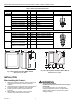


M6410A,M7410F,M6435A,M7435F ACTUATORS V5852A, V5853A, V5862A, V5863A VALVES
7 62-0100—9
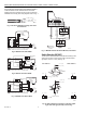
Switch Selection (M7435F)
The two built-in selector switches must be set according to the
desired valve action and the controller output signal (0 to 10V
or 2 to 10V). See Fig. 13.
Fig. 13. Switch selection according to controller output
signal and valve type
(two-way or three-way).
Input Signal Override (M7410F)
To override the controller output signal, connect the input
signal wire with COM (0%) or 24V (100%), see Fig. 14, using
an external relay.
If the temperature falls below a certain point; for example,
32°F (0°C), a relay can switch the 24 Vac to the Y connection
(0 to 10V, 2 to 10V). This opens or closes the valve.
OPERATION
Apply power to the actuator to drive the synchronous motor to
turn a screw spindle that opens or closes the valve. The
actuator is attached to the valve by a hand-tightened coupling
ring and a magnetic coupling that limit the gear assembly
torque and the actuator driving force.
The actuator pushes the center stem of the valve down,
compressing the valve spring and closing the valve. When the
actuator reverses, the valve spring expands, opening the
valve and pushing the center stem up.
The valves are supplied with a threaded plastic protective
cover/manual handle to protect the stem and to allow for
manual operation. Use the protective cover/manual handle to
fill the system during initial installation.
Turning the protective cover/manual handle:
— Clockwise: pushes the center stem of the valve down,
compressing the valve spring and closing the valve.
— Counterclockwise: allows the spring to expand, pushing
the center stem up and opening the valve.
Fig. 14. Input signal override for frost protection.
NOTES:
— You can also use the protective cover/handle for
heating/cooling with neither a controller nor
actuator during the building construction phase.
— Retain the protective cover. It can be needed for
future manual operation.
Commissioning
A microprocessor within the actuator maintains accurate
control/positioning by recommissioning itself every 24 hours
or whenever power is applied or interrupted. When power is
applied, the actuator drives to 0 and then to its starting
position according to the starting/input signal. The initial
commissioning or 24-hour recommissioning takes between
2.5 and 5 minutes, depending on the position of the actuator.
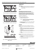
Valve Flow
TWO-WAY VALVES
In the two-way valves, the direction of flow is always from inlet
port to outlet port as indicated by the arrows on the valve body
(see Fig. 15).
THREE-WAY VALVES
Three-way valves are designed to be used as mixing valves.
This means that port AB is the total flow outlet; port A is the
controlled flow inlet; and port B is the bypass inlet (see
Fig. 16).
0 ... 10V2 ... 10V
W2
10V
10V
M22023
W1
M8226B
2
3
1
= 0 / 2 ... 10V
24 V
2
3
1
= 0 / 2 ... 10V
24 V