
Submittal Sheet


M6410A,M7410F,M6435A,M7435F ACTUATORS V5852A, V5853A, V5862A, V5863A VALVES
62-0100—9 B.B. Rev. 4-04 www.honeywell.com
Printed in U.S.A. on recycled
paper containing at least 10%
post-consumer paper fibers.
Automation and Control Solutions Honeywell International Honeywell Europe S.A. Honeywell Latin American
Honeywell International Inc. Honeywell Limited-Honeywell Limitée Control Products 3 Avenue du Bourget
Region
1985 Douglas Drive North 35 Dynamic Drive Honeywell Building 1140 Brussels 480 Sawgrass Corporate Parkway
Golden Valley, MN 55422 Scarborough, Ontario 17 Changi Business Park Central 1 Belgium Suite 200
M1V 4Z9 Singapore 486073 Sunrise FL 33325
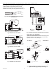
Fig. 15. Two-way valve operation block diagram.
Fig. 16. Three-way valve operation block diagram.
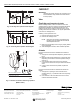
Fig. 17. Direction of actuator stem during operation
(M6410 shown).
CHECKOUT
IMPORTANT
Operating the system through one complete cycle is
recommended to verify that the valve and actuator
function properly.
Valve
Check
Body and Connections for Leaks
Before installing actuator, make sure that the valve stem
operates freely by using the protective cover/manual handle.
Impaired stem operation can indicate that the body was
twisted by faulty piping or that the stem was bent by rough
handling. Either of these conditions can require replacement
of the valve or cartridge insert.
If leaking or other problems occur:
1. Remove pressure from the valve.
2. Remove the cartridge insert.
NOTE: Instructions for removing and replacing the
cartridge insert are packed with the WV108
Insert Replacement Tool.
3. Make sure the cartridge insert O-ring is properly seated
and not damaged.
4. After installing the actuator, check actuator operation.
Actuator
Perform a functional checkout of the M6410A Actuator as
follows:
1. Change the room temperature setpoint by at least 10°F
(6°C).
2. Make sure the actuator either opens or closes the valve,
depending on the direction of the temperature change.
See Fig. 17.
3. If the actuator stem moves in the wrong direction,
reverse the connections for the open and close actuator
wires.
4. If step 3 does not resolve the problem, replace the
actuator.
Perform a functional checkout of the M7410F Actuator as
follows:
1. Change the Y input signal. The movement of the
actuator stem (Fig. 17) indicates if the valve is opening
or closing.
2. If the direction of the valve stem travel is not correct,
reset the direct/reverse switch.
OUTLET
INLET
+
–
+
–
M5357A
INLET
OUTLET
AB
B
A
+
– AB
B
A
+
–
M5358
M5292C
DIRECTION OF ACTUATOR STEM
OPERATION OF TWO-WAY VALVE
OPERATION OF PORT A-AB
OF THREE-WAY VALVE
OPENING
CLOSING
CLOSING
OPENING