
Submittal Sheet


M6410A,M7410F,M6435A,M7435F ACTUATORS V5852A, V5853A, V5862A, V5863A VALVES
3 62-0100—9
Actuator Required:
M6410A: Non-Spring Return Valve Actuator (3-position floating).
M6435A: Spring Return Valve Actuator (3-position floating;
stem retracts upon power failure).
M7410F: 0 to 10 Vdc or 2 to 10 Vdc Electronic Actuator, or
M7435F: Spring Return Valve Actuator (modulating control;
stem retracts upon power failure).
MP958: Pneumatic Valve Actuator.
Valve inserts are provided as spare parts. See Table 2.
Rangeability:
Two-way Valve: 50:1.
Three-way Valve: 50:1 for controlled port (A to AB).
Flow Characteristic:
V5853, V5863: A to AB: Equal Percentage.
B to AB: Linear.
V5852, V5862: Equal percentage.
Valve Cv Rating: See Table 1.
NOTE: To determine the capacity index (Cv) needed for your
application, use the following formula: Cv = gallons
per minute divided by the square root of the pressure
drop across the valve when the valve is fully open.
Valve Close-off Rating: See Table 1.
Body Material:
Red Brass: 1/2 in., three-way.
3/4 in., two- and three-way.
Yellow Brass: 1/2 in., two-way.
Stem and Plug Assembly:
Stem: Stainless steel.
Plug: Brass.
Table 1. Valve Close-off Ratings.
a
The Cv for the bypass port (B) on all three-way valves is
reduced by one Cv level. Example: A Port Cv = 0.47;
B Port Cv = 0.29. This feature eliminates the need for a
balancing valve with the load matched to the proper Cv.
b
For V5853A1XXX and V5863A1XXX Valves (Series 1000).
c
For V5853A2XXX and V5863A2XXX Valves (Series 2000).
IMPORTANT
Mount all valve types in return flow. When delta p-
values exceed 8.70 psi (60 kPa), noise can develop.
Approvals (Actuators): Underwriters Laboratories Inc. listed
for plenum use (UL94-5V).
Accessories and Replacement Parts:
WV108B Brush Tool for valve seat cleaning (used with WV108
tool).
WV108M Insert Replacement Tool, for replacing cartridge
insert without draining system.
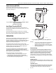
Fig. 1. Dimensions of V5852A, V5853A, V5862A and V5863A in in. (mm).
Pipe Size in
in. (mm)
C
v
a
Close-off Rating (psi)
Two-way Three-way
1/2 (13) 0.19 232 —
0.29 232 116
0.47
0.74 232 36
1.2 174
1.9 174 34
3/4 (19) 2.9 58
34
b
or 15
c
4.9
M7559A
INLET
OUTLET
PORT A
PORT AB
PORT B
A
B
C
STROKE
V5852/V5862
V5853/V5863
3 (77)
3-1/2 (88)
3/4 (19)
1 (25)
1-5/16 (34)
1-1/2 (38)
1-5/16 (34)
1-1/4 (32)
1/2 (13)
3/4 (19)
D
E
D
B
STROKE
B
B
A
C
1/2 (13)
3/4 (19)
3 (77)
3-1/2 (88)
3/4 (19)
1 (25)
1-5/16 (34)
1-1/4 (32)
B
FLOW DIAGRAM
A
BC
1/2 (13)
3/4 (19)
5/8 (16)
7/8 (22)
D
(NPT)
A
B
C
D
FLOW DIAGRAM
1/4
(6.5)
1/4
(6.5)
23/32
(18)
23/32
(18)
1-3/16 (30)
1-3/16 (30)
NOTE: SOLDER ENDS CONFORM TO ANSI B16-18.
D
(SWEAT)
1/2 (13)
3/4 (19)
5/8 (16)
7/8 (22)
E
(NPT)
E
(SWEAT)
VALVE
SIZE
VALVE
SIZE