
Submittal Sheet


M436A/M836A,B DAMPER MOTORS
60-2119—4
4
4-3/16
(106)
3-9/16
(91)
1-31/64
(38)
2-3/32
(53)
11/32
(9)
1/2
(13)
3-5/8 (92)
M9944
5/16
(8)
1-3/4 (45)
2-11/32 (60)
19/32
(15)
13/64 (5) DIAMETER (2)
13/64 (5) DIAMETER
3-3/4 (96) 1-7/16
(37)
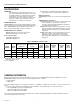
Fig. 2. 128336, 128499 Mounting Brackets dimensions in
in. (mm).
M9949
CLEARANCE HOLES FOR
MOUNTING SCREWS (4)
1-3/4
(46)
19/64 (8)
DIAMETER (2)
1-1/4 (32)
DIAMETER
7/16 (11)
CLEARANCE
HOLES (10)
2-3/8
(61)
4-23/32 (120)
2-3/8
(61)
1-3/16
(30)
2-35/64
(65)
1-1/2 (38) 1-3/8 (35)2-13/64 (61)
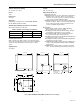
Fig. 3. 126809 Bracket dimensions in in. (mm).
INSTALLATION
When Installing this Product...
Read these instructions carefully. Failure to follow them
could damage the product or cause a hazardous
condition.
Check the ratings and descriptions given on the product
to make sure the product is suitable for your application.
Installer must be a trained, experienced service
technician.
After installation is complete, check out product
operation as provided in this specification.
CAUTION
1. Disconnect power supply before installation to
prevent electrical shock or equipment damage.
2. To prevent damage to the gear train, never turn the
motor shaft by hand or with a wrench.
3. Do not install the actuator in areas with acid fumes
or other deteriorating vapors that might attack the
metal parts of the motor.
4. Do not install the actuator in areas with escaping
gas or other explosive vapors that could be ignited
by a spark from the actuator or attached
accessories.
Location and Mounting
IMPORTANT
Mount M436 and M836 Damper Motors with the
shaft in the horizontal position.
Install the motor in a location free from acid fumes or other
deteriorating vapors that might attack the metal parts of the
motor. Also, make sure the location is free from escaping gas
or other explosive vapors that could be accidentally ignited by
a spark from the motor or its attached parts.
Install the motor in a location that allows enough clearance for
mounting accessories and for servicing.
Mounting brackets and crankarm drives are furnished with
TRADELINE® models of these motors or can be ordered
separately if required for the installation. Refer to the
Accessories section for specifications, Fig. 2 and 3 for
dimensions, and Fig. 4 through 7 for installation drawings.
Fig. 4. Exploded view showing how to mount 7640JE
Damper Shaft Coupling and 7640JM Mounting Bracket
Assembly to motor.
M9946
BUSHING FOR
1/4 INCH (6.5 mm)
DAMPER SHAFT
BUSHING FOR
3/8 INCH (9.5 mm)
DAMPER SHAFT
CLAMP
ADAPTER
FOR
DAMPER
COUPLING
OPEN CLOSE
126809
BRACKET