
Submittal Sheet
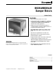


M436A/M836A,B DAMPER MOTORS
60-2119—4
6
ADJUSTMENT AND CHECKOUT
Auxiliary Switch Adjustment
Adjust the internal spdt auxiliary switch of the M436/M836
Damper Motor to operate at any point between 5 degrees and
70 degrees of the motor stroke. The switch has a 1 to 2 degree
nonadjustable differential. The switch makes R to B contact
during the power stroke (motor shaft moves in the direction of
the OPEN arrow on the outside of the case).
Apply power to the motor so that the motor runs to the OPEN
position. Note the point of the motor stroke where the switch
operates (audible click or check for continuity across the R to B
terminals) If the switch operates correctly for the application,
proceed to check out the installation. If the switch needs to be
adjusted, perform the following steps:
Determine the number of degrees that the switch cam
must be adjusted to operate the switch at the desired
point of the motor stroke.
IMPORTANT
Do not adjust switch to operate closer than
five degrees from the ends of the motor stroke.
Remove the motor cover.
CAUTION
To prevent electrical shock or equipment damage,
disconnect the power supply before adjusting the
switch cam.
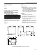
Insert a narrow bladed common-point screwdriver in a
slot in the switch cam (white plastic) located near the
center of the motor. Refer to Fig. 10. Each slot in the cam
equals approximately 20 degrees of motor rotation.
Select a reference point and move the cam the correct
number of degrees, as follows:
a. To adjust the switch to operate nearer the open
(maximum rotation) motor position, move the cam
in the direction of the CLOSE arrow on the
outside of the motor case.
b. To adjust the switch to operate nearer the closed
motor position, move the cam in the direction of
the OPEN arrow on the outside of the motor case.
Repower the motor and check the point at which the switch
makes and breaks. Readjust as necessary.
Fig. 10. Using screwdriver to adjust auxiliary switch cam.
Checkout
Operate the motor through the complete open-close stroke.
Be prepared to release one of the previously tightened
linkage connections, if necessary, to prevent damage. Check
for proper operation, making sure that the linkage does not
bind and that the motor travels smoothly through the fully
open and fully closed positions. Cut any excess linkage rod
length to the correct size.
Make necessary minor adjustments until desired operation is
obtained and tighten all nuts and setscrews. A motor
checkout should prove that:
The motor operates the load.
The motor responds properly to the controller.
There is no linkage binding or motor stalling at any
point of travel.
If the motor does not operate properly, check for proper
voltage or mechanical linkage or damper binding.
OPEN CLOSE
M9947