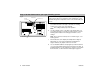
MagicStat® CT3200 Programmable Thermostat Installation and Programming Instructions Weekday/Weekend (5-day/2-day) Programmable Heat and/or Cool Low Voltage (20 to 30 Vac) Thermostat and Mounting Plate Model CT3200 Table of Contents Welcome to the world of comfort and energy savings with your new Honeywell MagicStat® Programmable Thermostat. Your new thermostat will automatically control the temperature in your home, keeping you comfortable while saving energy.
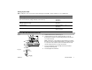
Recycling Thermostat Fig. 1 MERCURY SWITCH If you are removing an old thermostat that contains mercury in a sealed tube (Fig. 1), do not place the old thermostat in the trash. Contact your local waste management authority for instructions regarding recycling and the proper disposal of the old thermostat. M3701 Installation Verify that you have the right thermostat Make sure that the CT3200 is the right thermostat for your heating/cooling system.
Step 1. Prepare for installation a. Carefully unpack your new thermostat. Save your receipt and make sure you have the following parts: • • b. Thermostat and mounting plate Labels Screws and anchors Installation and Programming Instructions Gather the needed tools and supplies listed below. Required tools and supplies • • • • c. • • Optional tools Two AA alkaline batteries. Honeywell recommends Energizer® • batteries.
Step 2. Remove the old thermostat Fig. 2 a. Turn off power to the heating/cooling system, either at the furnace or at the fuse/circuit breaker panel. b. Remove the cover of your old thermostat (Fig. 2). c. Unscrew and remove the old thermostat’s mounting plate from the wall, but do not disconnect the wires. d. Inspect the old thermostat wiring. If the wiring meets any of the following conditions, see the special wiring instructions on page 9.
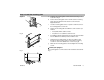
Step 3. Install the mounting plate Fig. 5 a. Separate the mounting plate from the thermostat using a coin, as shown in Fig 5. b. Position the mounting plate on the wall. Be sure the mounting plate sits flush against the wall and none of the wires are trapped behind it. c. Level the mounting plate and use a pencil to mark the center of the mounting plate’s screw holes. d. Remove the mounting plate and drill holes at the locations you marked. M20139 Fig.
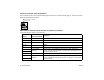
Step 4. Set the thermostat for your type of heating system Fig. 8 IMPORTANT: Setting your thermostat correctly for your type of heating system allows it to maintain accurate temperature control, minimize swings in the temperature of the room, and efficiently run the fan.
Heating System Table Note: Setting the screw “out one turn” means turning the screw 360° counter-clockwise, or one complete turn. Type of system Screws A and B Fuel switch Warm air, gas, or oil heating system with an efficiency rating under 90%. (The furnace efficiency rating should be on the furnace.
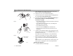
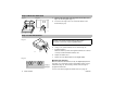
Step 6. Mount the thermostat Fig. 11 Fig. 12 a. Align the tabs at the top of the thermostat with the tabs at the top of the mounting plate (Fig. 11). b. Press the lower edge of the case to latch the bottom of the thermostat (Fig. 12). M20131 M20130 Step 7. Install the batteries IMPORTANT: Batteries must be installed for programming and operation of the thermostat and heating/cooling system. Honeywell recommends using Energizer® batteries. Fig. 13 M1719C Fig. 14 REMOVING BATTERY DOOR a.
Special wiring instructions A clock thermostat with C or C1 terminals A clock thermostat has one or two extra wires attached to the C or C1 terminals that allow the clock to operate. These wires are not used during the installation of your new 3200 thermostat and must be insulated from each other to avoid damaging your electrical circuit. a. Make sure that power to the heating/cooling system is turned off. b. Locate the wires that are connected to the clock terminals marked C or C1. c.
Five wires connected to the old thermostat Your new thermostat has a factory-installed metal jumper between the R and Rc terminals (Fig. 15). Remove the jumper before wiring the R and Rc terminals. JUMPER (FACTORYINSTALLED). REMOVE IF 5-WIRE SYSTEM Fig. 15 Rc R M20127 W Y G Old thermostat terminals that do not match new thermostat terminals Use the table below to wire the new thermostat.
Programming Faceplate illustration and descriptions Fig.
Step 1. Set the current time and day Fig. 17 a. Press once. The time is displayed (Fig. 17). b. Press and hold displayed. or until the current time is Fig. 18 c. Press again. The day is displayed (Fig. 18). d. Press and hold displayed. or until the current day is Fig. 19 e. Press once. The current time and day and the current temperature are displayed (Fig. 19). Step 2.
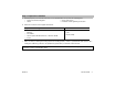
Program period Description When available WAKE The time when you get up and get ready to leave your home. You can set the system at a comfortable temperature for this period. Weekdays and weekend LEAVE The time when you are regularly away from home. You can set up an energy-saving temperature for this period. Weekdays only The time between returning home and going to bed. You can set the system at a comfortable temperature for this period. Weekdays only The time when you are sleeping.
Step 3. Program the heating schedule a. Write in the times and temperatures that you want to program for your heating schedule. Heating Schedule Suggested Settings Program period WAKE LEAVE RETURN SLEEP Time 6:00 AM 8:00 AM 6:00 PM 10:00 PM Temp 70°F (21°C) 62°F (16.5°C) 70°F (21°C) 62°F (16.5°C) Weekday (Mon–Fri) Time Weekend (Sat–Sun) Time Temp Temp b. Set the System switch to HEAT. c. Press once. A blank schedule is displayed (Fig. 20). d.
Fig. 23 g. Press (Fig. 23). h. Set the Saturday and Sunday WAKE time by pressing or i. until the weekend schedule is displayed until the desired time is displayed. Fig. 24 Set the Saturday and Sunday WAKE temperature by pressing or is displayed (Fig. 24). until the desired temperature j. Press again to display a blank schedule for the SLEEP program period and repeat steps h. through j. to set the program. k. Press to start the program. Step 4. Program the cooling schedule a.
b. Set the System switch to COOL. c. Repeat steps 3c. through 3k. to program the weekday and weekend cooling schedule. Step 5. Check out the system Verify that your heating system works a. Set the System switch to HEAT, and the Fan switch to AUTO. b. Press until the setting is 10°F (6°C) above room temperature (Fig. 25). Your heating system should start and the fan should run after a short delay. c. Press until the setting is 10°F (6°C) below room temperature. Your heating system should shut off.
f. Press until the setting is 10°F (6°C) above room temperature. Your cooling system and fan should stop. g. Set the System switch to OFF and the Fan switch to AUTO. The cooling system and fan should be off. Operation Change the clock for Daylight/Standard time a. Press once. The time is displayed. b. Press and hold c. Press once. The current time and day and the current temperature are displayed. or until the correct time is displayed.
Switch Setting Result System Cool The thermostat controls your air conditioning system. Off Both the heating and air conditioning systems are off. Heat The thermostat controls your heating system. Replace the batteries As the batteries run low, your thermostat shows the following in the digital display: If you see: Batteries are: You should: Flashing “bAt Lo” Low Replace the batteries as soon as possible, within the month. Steady “bAt Lo” Almost dead Replace the batteries immediately.
Override the program settings Note: Make sure the System switch is set to either HEAT or COOL before making any changes to the schedule. Change the temperature temporarily Press displayed. or until the desired temperature is Fig. 27 An arrow is displayed indicating that the change is temporary (Fig. 27). Note: A temporary change to the temperature lasts for the current program period only. The heating/cooling schedule that you programmed resumes when the next scheduled program period is reached.
Check the current programmed temperature Press to display the temperature that is programmed for the current program period. The SET indicator displays briefly along with the programmed temperature (Fig. 29). The display then returns to the room temperature. Fig. 29 Check programs Press repeatedly to display the times and temperatures that you programmed. Press to resume the program. Cancel a program a. Press 30). b. Press and simultaneously.
Frequently asked questions If... Then... Display will not come on • • Make sure the batteries are fresh and installed correctly. Set the System switch to OFF. Remove the batteries and then insert them backwards for five to ten seconds to reset the thermostat. Replace the batteries correctly. The display should come on. Temperature display will not go lower than 45°F (7°C) or higher than 88°F (31°C) during programming • You have reached the temperature limit. The setting range is 45°F–88°F (7°C–31°C).
If... Then... Cooling will not come on • • • • • • Check that the System switch is set to COOL. Check the system fuse or circuit breaker and replace or reset if necessary. Check for correct wiring and good connections. If display is blank or says “bAt Lo,” install fresh batteries. The thermostat has a built-in time delay on cooling. Allow 5 to 10 minutes after changing the setting before the air conditioner starts.
Limited warranty Honeywell warrants this product, excluding battery, to be free from defects in the workmanship or materials, under normal use and service, for a period of one (1) year from the date of purchase by the consumer. If, at any time during the warranty period, the product is defective or malfunctions, Honeywell shall repair or replace it (at Honeywell’s option) within a reasonable period of time.
Home and Building Control Honeywell 1985 Douglas Drive North Golden Valley, MN 55422 Home and Building Control Honeywell Limited–Honeywell Limitée 35 Dynamic Drive Scarborough, Ontario M1V 4Z9 69-0653-6 Rev. 9-01 Printed in the U.S.A. www.honeywell.