00-02408D_unit_7120_Cover_Oct_2005.qxd 10/26/2005 11:31 AM Page 1 METROLOGIC INSTRUMENTS, INC.
Copyright © 2005 by Metrologic Instruments, Inc. All rights reserved. No part of this work may be reproduced, transmitted, or stored in any form or by any means without prior written consent, except by reviewer, who may quote brief passages in a review, or provided for in the Copyright Act of 1976. Products and brand names mentioned in this document are trademarks of their respective companies.
TABLE OF CONTENTS Introduction................................................................................................1 Scanner and Accessories..........................................................................2 Operational Notes .....................................................................................3 Installation For RS232, OCIA and IBM 46XX Interfaces.........................................4 For Keyboard Wedge Interface ........................................................
TABLE OF CONTENTS Installing the Optional Wall/Counter Mount .............................................21 Troubleshooting Guide ............................................................................22 RS-232 Demonstration Program .............................................................27 Applications and Protocols ......................................................................28 Design Specifications ..............................................................................
INTRODUCTION Orbit® is an aggressive, omnidirectional laser bar code scanner. Lightweight and rugged, Orbit is small in size, but BIG in performance. Designed for applications where counter space is limited, Orbit is the ideal presentation scanner for retail, convenience, liquor and specialty stores. In addition, Orbit’s unique, contoured shape allows it to be picked-up and used as a hand-held scanner when scanning large or bulky items.
SCANNER AND ACCESSORIES BASIC KIT Part # Description ® MS7120 Orbit Presentation Laser Scanner 00-02407 MetroSelect Programming Guide 00-02408 MS7120 Installation and User’s Guide* ® * Available on the Metrologic website - www.metrologic.com OPTIONAL ACCESSORIES Part # Description AC to DC Power Transformer- Regulated 5.2VDC @ 650 mA output.
SCANNER AND ACCESSORIES OPTIONAL ACCESSORIES Part # Description MVC** Metrologic Voltage Converter Cable +12VDC to +5.2VDC or -12VDC to +5.2VDC MX009-2** MX009 USB Converter Cable ** Contact a Metrologic customer service representative for additional information on the MVC and MX009 cable series and the host connections available. 45-45619 Counter/Wall Mount Kit Other items may be ordered for the specific protocol being used.
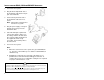
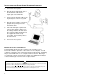
INSTALLATION FOR RS232, OCIA AND IBM 46XX INTERFACES 1. Turn off the host system. 2. Plug the male 10-pin RJ45 end of the PowerLink cable into the 10-pin jack on the MS7120. 3. Connect the 9 pin female end of the PowerLink cable to the host device. Note: Skip to #6 if receiving power from the host system. 4. Plug the power supply’s L-shaped plug into the power jack on the PowerLink cable. 5. Check the AC input requirements of the power supply to make sure the voltage matches the AC outlet.
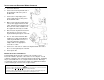
INSTALLATION FOR KEYBOARD WEDGE INTERFACE 1. Turn off the PC/Host. 2. Connect the male 10-pin RJ45 end of the PowerLink cable to the jack on the MS7120. 3. Connect the L-shaped plug of the power supply into the power jack on the PowerLink cable. 4. Make sure the AC input requirements of the power supply matches the AC outlet. Plug the power supply into the AC outlet. The outlet should be near the equipment and easily accessible. 5. Disconnect the keyboard from the PC.
INSTALLATION FOR STAND ALONE KEYBOARD INTERFACE 1. Turn off the host system. 2. Plug the male 10-pin RJ45 end of the PowerLink cable into the 10-pin jack on the MS7120. 3. Connect the PowerLink cable to the keyboard port on the host system. 4. Plug the power supply’s L-shaped plug into the power jack on the PowerLink cable. 5. Check the AC input requirements of the power supply to make sure the voltage matches the AC outlet. The outlet should be installed near the equipment and be easily accessible.
INSTALLATION NOTES FOR USB INTERFACE Metrologic’s MX009 USB cable is a device that converts serial RS232 formatted data to either USB Keyboard or USB Point-of Sale communication protocol. Please refer to the MX009 USB Converter Cable Programming Guide (MLPN 00-02574A) supplied with your MX009 cable for detailed installation and programming guidelines. INSTALLATION NOTES FOR MS7120-00 LASER EMULATION MS7120-00 Only The MS7120-00 leaves the factory with the Laser Emulation Mode enabled.
SCANNER PARTS Red LED On a successful read of a bar code, the red LED will turn ON. After communication to the host is complete, the red LED will turn OFF. Refer to Visual Indicators and Audible Indicators for additional information. Green LED During normal operation, the green LED is ON. This indicates that the laser is on and the unit is ready to scan. The LEDs are also used as diagnostic indicators and mode indicators. Refer to Visual Indicators and Audible Indicators for additional information.
AUDIBLE INDICATORS When the MS7120 scanner is in operation, it provides audible feedback. These sounds indicate the status of the scanner. Eight settings are available for the tone of the beep (normal, 6 alternate tones and no tone). To change the tone, refer to the MetroSelect® Programming Guide (MLPN 00-02407B) or the MetroSet2 help files. One Beep When the scanner first receives power, the green LED will turn on, then the red LED will flash and the scanner will beep once.
VISUAL INDICATORS There is a red LED and a green LED on the head of the MS7120. When the scanner is on, the flashing or constant illumination of the LEDs indicates the status of the current scan and the scanner. No Red or Green LED The LEDs will not be illuminated if the scanner is not receiving power from the host or transformer. Steady Green When the laser is active, the green LED is illuminated. The green LED will remain illuminated until the laser is deactivated.
FAILURE MODES Flashing Green and One Razzberry Tone This indicates the scanner has experienced a laser subsystem failure. Return the unit for repair at an authorized service center. Flashing Red and Green and Two Razzberry Tones This indicates the scanner has experienced a motor failure. Return the unit for repair at an authorized service center. Continuous Razzberry Tone with both LEDs off If, upon power up, the scanner emits a continuous razzberry tone, then the scanner has an electronic failure.
LABELS Each scanner has three labels on the bottom of the unit. These labels contain information such as; the model number, date of manufacture, serial number, laser class and caution statements. The following illustrations show the location and content of the three labels. MAINTENANCE Smudges and dirt can interfere with the proper scanning of a bar code. Therefore, the output window will need occasional cleaning. 1. 2. 12 Spray glass cleaner onto lint free, non-abrasive cleaning cloth.
SCAN VOLUME SPECIFICATIONS Specifications based on 100% UPC Bar Codes.
SCAN VOLUME SPECIFICATIONS (CONT.) Specifications based on 100% UPC Bar Codes.
SCAN VOLUME SPECIFICATIONS (CONT.) Specifications based on 100% UPC Bar Codes.
DEPTH OF FIELD BY MINIMUM BAR CODE ELEMENT WIDTH Optimal Low Density (Default) 0 B & Distance: Scanner Face To Bar Code (mm) & 00 0 0 0 Width of Scan Field (mm) Minimum Bar Code Element Width mm mils 16 A .13 5.2 B .15 5.7 C .16 6.3 D .17 6.8 E .19 7.5 F .23 9 G .25 10 H .33 13 J .53 21 K .
DEPTH OF FIELD BY MINIMUM BAR CODE ELEMENT WIDTH Optimal High Density B D & Distance: Scanner Face To Bar Code (mm) & 0 0 0 Width of Scan Field (mm) Minimum Bar Code Element Width mm mils A .13 5.2 B .15 5.7 C .16 6.3 D .17 6.8 E .19 7.5 F .23 9 G .25 10 H .33 13 J .53 21 K .
DEPTH OF FIELD BY MINIMUM BAR CODE ELEMENT WIDTH Close D 0 Distance: Scanner Face To Bar Code (mm) Width of Scan Field (mm) Minimum Bar Code Element Width mm mils 18 B .15 5.7 C .16 6.3 D .17 6.8 E .19 7.5 F .23 9 G .25 10 H .33 13 J .53 21 K .
DEPTH OF FIELD BY MINIMUM BAR CODE ELEMENT WIDTH Normal 0 0 D Distance: Scanner Face To Bar Code (mm) & & 00 Width of Scan Field (mm) Minimum Bar Code Element Width mm mils A .13 5.2 B .15 5.7 C .16 6.3 D .17 6.8 E .19 7.5 F .23 9 G .25 10 H .33 13 J .53 21 K .
DEPTH OF FIELD BY MINIMUM BAR CODE ELEMENT WIDTH Far D 0 Distance: Scanner Face To Bar Code (mm) & 00 0 Width of Scan Field (mm) Minimum Bar Code Element Width mm mils 20 A .13 5.2 B .15 5.7 C .16 6.3 D .17 6.8 E .19 7.5 F .23 9 G .25 10 H .33 13 J .53 21 K .
INSTALLING THE OPTIONAL WALL/COUNTER MOUNT Kit #45-45619 contains: a. b. c. d. 1. Locking Plate [MLPN 50-50302] ............................ Qty. 1 Base Cover [MLPN 50-50301] ............................ Qty. 1 Wood Screw, #7 x 1.00” [MLPN 18-18013] ............................ Qty. 3 Flathead Screw, M3 x 8 mm [MLPN 18-18004] ............................ Qty. 4 a. c. d. b. Fig. 1 Drill mounting holes Note the position Orbit will rest (fig. 2).
TROUBLESHOOTING GUIDE The following guide is for reference purposes only. Contact a Metrologic representative at 1-800-ID-METRO or 1-800-436-3876 to preserve the limited warranty terms on page 39. All Interfaces MS7120 Series Troubleshooting Guide SYMPTOMS POSSIBLE CAUSE(S) SOLUTION No LEDs, beep or motor spin No power is being supplied to the scanner Check transformer, outlet and power strip.
TROUBLESHOOTING GUIDE (CONTINUED) SYMPTOMS POSSIBLE CAUSE(S) SOLUTION The unit powers up, but does not scan and/or beep Beeper disabled. No tone selected Enable beeper. Select tone The unit powers up, but does not scan and/or beep Scanning a particular symbology that is not enabled UPC/EAN, Code 39, interleaved 2 of 5, Code 93, Code 128 and Codabar are enabled by default.
TROUBLESHOOTING GUIDE (CONTINUED) SYMPTOMS POSSIBLE CAUSE(S) SOLUTION Scanner beeps at some bar codes and NOT for others of the same bar code symbology The print quality of the bar code is suspect Check print mode. The type of printer could be the problem. Change print settings. For example change to econo mode or high speed Scanner beeps at some bar codes and NOT for others of the same bar code symbology The aspect ratio of the bar code is out of tolerance Check print mode.
TROUBLESHOOTING GUIDE (CONTINUED) Keyboard Wedge Only SYMPTOMS POSSIBLE CAUSE(S) SOLUTION The unit scans the bar code but there is no data Configuration is not correct Make sure the scanner is configured for the appropriate mode. Check internal jumper The unit scans but the data is not correct Configuration is not correct Make sure that the proper PC type AT, PS2 or XT is selected. Verify correct country code and data formatting are selected.
TROUBLESHOOTING GUIDE (CONTINUED) RS-232 Only SYMPTOMS POSSIBLE CAUSE(S) SOLUTION Power-up OK and scans OK but does not communicate properly to the host Com port at the host is not working or configured properly Check to make sure that the baud rate and parity of the scanner and the communication port match and the program is looking for “RS-232" data Power-up OK and scans OK but does not communicate properly to the host Cable not connected to the proper com port Check to make sure that the baud rat
RS-232 DEMONSTRATION PROGRAM If an RS-232 scanner is not communicating with your IBM compatible PC, key in the following BASIC program to test that the communication port and scanner are working. This program is for demonstration purposes only. It is only intended to prove that cabling is correct, the com port is working, and the scanner is working. If the bar code data displays on the screen while using this program, it only demonstrates that the hardware interface and scanner are working.
APPLICATIONS AND PROTOCOLS The model number on each scanner includes the scanner number and factory default communications protocol.
DESIGN SPECIFICATIONS MS7120 SPECIFICATIONS OPERATIONAL Light Source: Depth of Field: Scan Speed: Scan Pattern: Scan Lines: Min Bar Width: VLD 640-660 nm 0 mm to 216 mm (0" to 8.5") for 0.33 mm (13 mil) bar codes 1067 scans/second 5 fields of 4 parallel lines (omnidirectional) 20 0.13 mm (5.
DESIGN SPECIFICATIONS MS7120 SPECIFICATIONS ELECTRICAL Input Voltage: Power: Operating Current: DC Transformers: Laser Class: EMC: 5.2VDC ± 0.25V 1.0 W typical 200 mA typical, 250 mA typical for IBM models Class II; 5.
DEFAULT SETTINGS Many functions of the scanner can be "programmed" - that is, enabled or disabled. The scanner is shipped from the factory programmed to a set of default conditions. The default parameter of the scanner has an asterisk ( * ) in the charts on the following pages. If an asterisk is not in the default column then the default setting is Off or Disabled. Every communication does not support every parameter.
DEFAULT SETTINGS Parameter DTS/NIXDORF Default * NCR F NCR S OCIA RS-232* Light Pen IBM 46XX KBW Laser Emulation ü ü ü ü ü ü ü ü ü ü ü ü ü ü ü ü ü ü ü ü ü ü ü ü ü ü ü ü ü ü ü ü ü ü ü ü ü ü ü ü ü ü ü ü ü ü ü ü ü ü ü ü ü ü ü ü ü ü Same Symbol Rescan Timeout: 1250 msecs ü ü ü ü ü ü Same Symbol Rescan Timeout: 2000 msecs ü ü ü ü ü ü ü ü Poll Light Pen Source Beeper Tone Normal Beep/Transmit Sequence Before Transmit Communication Timeout None Razzberry Tone
DEFAULT SETTINGS Light Pen IBM 46XX KBW ü ü ü ü ü ü ü ü ü ü ü ü ü ü ü ü ü ü ü ü Transmit Mod 43 Check Digit on Code 39 ü ü ü ü ü ü ü ü ü ü ü ü Transmit Code 39 Stop/Start Characters ü ü ü ü Transmit Mod 10/ITF ü ü ü ü Transmit MSI-Plessey Check Characters ü ü ü ü Parameter Default OCIA RS-232* Transmit UPC-A Number System * ü ü Transmit UPC-A Manufacturer ID# * Transmit UPC-A Item ID# * Convert EAN-8 to EAN-13 Transmit Codabar Start/Stop Characters CLSI Editing
DEFAULT SETTINGS Parameter Default OCIA RS-232* Light Pen IBM 46XX KBW Carriage Return * ü ü Line Feed - disabled by default in KBW * ü ü Tab Prefix ü ü Tab Suffix ü ü "DE" Disable Command ü "FL" Laser Enable Command ü DTR Handshaking Support ü RTS/CTS Handshaking ü Character RTS/CTS Laser Emulation ü * Message RTS/CTS ü XON/XOFF Handshaking ü ACK/NAK ü ü ü as code 39 ü ü as code 39 ü as code 39 as code 39 as code 39 ü ü as code 39 ü ü ü ü ü ü Two Digit
DEFAULT SETTINGS Parameter Default Coupon Code 128 Programmable Code Lengths 7 avail. Programmable Prefix Characters 10 avail. OCIA RS-232* Light Pen IBM 46XX KBW Laser Emulation ü ü as code 39 ü ü as code 39 ü ü ü ü ü ü ü ü ü ü ü ü Suffix Characters Prefixes for individual Code Types ü Editing Inter Scan-Code Delay Programmable (100 msec steps) ü ü 800 msec Function/Control Key Support Minimum Element Width Programmable in 5.
SCANNER AND CABLE TERMINATIONS Scanner Pinout Connections The MS7120 scanner interfaces terminate to a 10-pin modular jack. The serial # label indicates the interface enabled when the scanner is shipped from the factory. Some units have internal jumpers that can be moved to enable a different electrical interface. Current combinations are listed below.
SCANNER AND CABLE TERMINATIONS MS7120-11 IBM 46XX/RS-232 Pin 1 2 3 4 5 6 7 8 9 10 Function Ground RS-232 Transmit Output RS-232 Receive Input RTS Output CTS Input DTR Input IBM 46XX transmit IBM 46XX Receive +5VDC Shield Ground 1 10 Options listed are program/cable selections Cable Connector configurations MLPN Pin 1 2 3 4 5 6 7 8 9 PowerLink Cable 54-54xxx* or 53-53xxx* Function Shield Ground RS-232 Transmit Output RS-232 Receive Input DTR Input Power/Signal Ground Reserved CTS Input RTS Output +5
SCANNER AND CABLE TERMINATIONS Cable Connector Configuration The PowerLink cable is terminated with a 5-pin DIN female connector on one end, and a 6-pin mini DIN male on the other. 4 2 5 1 2 3 1 4 3 6 5 PowerLink Cable 5-Pin DIN, Female 6-Pin DIN, Male Metrologic will supply an adapter cable with a 5-pin DIN male connector on one end and a 6-pin mini DIN female connector on the other.
LIMITED WARRANTY The MS7120 Orbit© scanners are manufactured by Metrologic at its Blackwood, New Jersey, U.S.A. facility. The MS7120 scanners have a two (2) year limited warranty from the date of manufacture. Metrologic warrants and represents that all MS7120 scanners are free of all defects in material, workmanship and design, and have been produced and labeled in compliance with all applicable U.S. Federal, state and local laws, regulations and ordinances pertaining to their production and labeling.
NOTICES Notices This equipment has been tested and found to comply with the limits for a Class B digital device, pursuant to part 15 of the FCC rules. These limits are designed to provide reasonable protection against harmful interference in a residential installation. This equipment generates, uses and can radiate radio frequency energy and, if not installed and used in accordance with the instructions, may cause harmful interference to radio communications.
NOTICES Achtung Die Verwendung anderer als der hier beschriebenen Steuerungen, Einstellungen oder Verfahren kann eine gefährliche Laserstrahlung hervorrufen. Der Kunde sollte unter keinen Umständen versuchen, den Laser-Scanner selbst zu warten. Sehen Sie niemals in den Laserstrahl, selbst wenn Sie glauben, daß der Scanner nicht aktiv ist. Öffnen Sie niemals den Scanner, um in das Gerät hineinzusehen. Wenn Sie dies tun, können Sie sich einer gefährlichen Laserstrahlung aussetzen.
NOTICES Die nachfolgende Mitteilung gilt nur für Modell Nr. MS7120-11 Zur Klassifizierung gemäß Klasse B nach FCC Teil 15, ICES-003 und EN55022, befestigen Sie den vorliegenden Ferritkern an dem mitgelieferte PowerLink Kabel Ihres MS7120-11 Barcode Scanners. Ferritkern Installation: 1. Entfernen Sie den vorliegenden Ferritkern aus der Schutzhülle. 2. Um den Ferritkern zu öffnen, führen Sie einen kleinen Schlitzschraubendreher in die rechteckige Öffnung und stemmen Sie den Ferritkern auf. 3.
NOTICES Nota (exclusivamente para los modelos de la serie MS7120-11) De acuerdo con las normativas FCC apartado 15, ICES-003 y EN55022 para la Clase B, el obturador de ferrita del PowerLink que se suministra con el modelo de lector de códigos de barras MS7120-11. Instalación del obturador de ferrita 1. Quitar el envoltorio protector del obturador de ferrita 2. Para abrir el obturador, introduzca un destornillador plano pequeño dentro de la abertura rectangular y deje el obturador abierto 3.
PATENTS This METROLOGIC product may be covered by one or more of the following U.S. Patents: U.S. Patent No.
INDEX A F accessories.......................... 2, 3 adapter....................... 2, 3, 5, 38 application.............................. 27 audible ..................................... 9 authorized service center....... 11 autodiscriminates................... 29 failure indicator ........................ 9 failure modes ..................... 9, 11 function .......... 22, 35, 36, 37, 38 B G green LED ............................. 10 ground ....................... 36, 37, 38 bar code..........
INDEX N S normal depth of field .............. 35 notices ................. 40, 41, 42, 43 scan lines............................... 29 scan pattern....................... 8, 29 scan speed ............................ 29 scanner installation.......... 4, 5, 6 SELV ............................... 4, 5, 6 shock ..................................... 30 specifications ........ 13-15, 29, 30 stand.......................... 2, 3, 6, 29 storage................................... 30 system interfaces ..........
October 2005 Printed in USA 00 - 02408D