
User`s guide

21
INSTALLING THE OPTIONAL WALL/COUNTER MOUNT
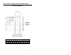
Kit #45-45619 contains:
a. Locking Plate
[
MLPN 50-50302] ............................ Qty. 1
b. Base Cover
[
MLPN 50-50301] ............................ Qty. 1
c. Wood Screw, #7 x 1.00”
[
MLPN 18-18013] ............................ Qty. 3
d. Flathead Screw, M3 x 8 mm
[
MLPN 18-18004] ............................ Qty. 4
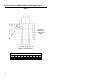
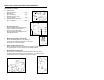
1. Drill mounting holes
Note the position Orbit will rest (fig. 2).
Use the dimensions provided in
figure 2 or the locking plate
[
MLPN 50-50302] as a template to drill
three #39 pilot holes.
2. Mount locking plate to wall/counter
Secure the locking plate [
MLPN 50-50302] to
the counter or wall with the three #7 x 1.00” wood
screws [
MLPN 18-18013] provided.
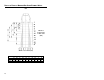
3. Attach the base plate to Orbit
Secure the base cover [
MLPN 50-50301] to the bottom of Orbit (fig. 4)
using the four M3 x 8 mm screws [
MLPN 18-18004] provided.
4. Mount Orbit to locking plate
Hold Orbit 90° clockwise from the desired position then lower it over
the locking plate until it sits flush to the countertop. Twist Orbit counter
clockwise 90°, as shown in figure 5, to lock unit in place.
a.
d.
b.
c.
Fig. 1
Position Indicators
Fig. 2
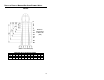
Fig. 3
Fig. 4
Fig. 5