
Submittal Sheet
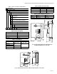
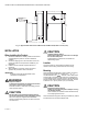
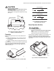
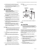
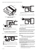
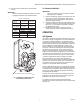
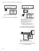
Table Of Contents

35 AND 70 LB-IN. NON-SPRING RETURN DIRECT COUPLED ACTUATORS
63-2209—9 8
Fig. 10. Conduit cover for ML6161C,D
and ML6174C,D DCA.
Fig. 11. ML6161 or ML6174 used with T87F in
heating-only or cooling-only application.
NOTE: See Fig. 12 for the 201052B Auxiliary Switch wiring.
Fig. 12. 201052B Auxiliary Switch wiring.
Fig. 13. ML7161 or ML7174 used with 2-10 Vdc control.
Fig. 14. ML7161 or ML7174 used with 4-20 mA control.
Auxiliary Switches
The 201052A or B Auxiliary Switch is used in conjunction with
the actuator. It allows for control of equipment external to the
actuator (for example, electric reheat coils and fan) at an
adjustable point in the stroke (0° to 90°) of the actuator.
The 201052A and B Auxiliary Switches are field-addable. For
mounting instructions, see form 63-2218, provided with the
device.
IMPORTANT
When operating an ML6161 or ML6174 from a two-
position controller, a 201052B Auxiliary Switch is
required for proper operation. See Fig. 12.
Auxiliary Potentiometers
The 200976A,C Auxiliary Potentiometers mount on the face of
the ML6161A,C or ML6174A,C (as shown in Fig. 15). The
potentiometer shaft has a slipping collar. If one of the two limits
of the potentiometer is exceeded, the collar continues to rotate,
causing no damage to the potentiometer itself. To mount the
potentiometer on the actuator:
1. Turn the potentiometer to align the shaft key with the slot
in the potentiometer drive.
2. Tilt the potentiometer slightly so the key faces down
toward the slot.
3. Insert the potentiometer into the slot, and push down so
the potentiometer is flush with the actuator body and the
bracket is aligned over the screw hole.
COVER
M10075
CONDUIT
KNOCKOUTS
M18019
EXTERNAL
SWITCH
R
W
Y
T87F
R8222
RED COM
BLUE CW
WHITE CCW
L1
(HOT)
L2
1
1
2
2
POWER SUPPLY. PROVIDE DISCONNECT MEANS AND OVERLOAD
PROTECTION AS REQUIRED.
AUXILIARY SWITCHES ARE REQUIRED TO TURN OFF THE MOTOR
AT EACH END OF THE STROKE.
ML6161, ML6174
M17350
SPDT
CONTROL
ON/OFF
CONTROL
RED COM
BLUE CW
WHITE CCW
L1
(HOT)
L2
1
1
4
2
3
2
3
4
POWER SUPPLY. PROVIDE DISCONNECT MEANS AND OVERLOAD
PROTECTION AS REQUIRED.
SET SWITCH TO CLOSE WHEN STROKE REACHES FULL CW POSITION.
SET SWITCH TO CLOSE WHEN STROKE REACHES FULL CCW POSITION.
ON-OFF CONTROL REQUIRES AN R8222 SPDT RELAY IN PLACE OF THE
SPDT CONTROL.
ML6161, ML6174
201052B
L1
(HOT)
L2
1
1
POWER SUPPLY. PROVIDE DISCONNECT MEANS AND OVERLOAD
PROTECTION AS REQUIRED.
2-10 Vdc CONTROLLER
ML7161, ML7174
T1
T2
–
–
+
+ mA
+ V
M18072
L1
(HOT)
L2
1
1
POWER SUPPLY. PROVIDE DISCONNECT MEANS AND OVERLOAD
PROTECTION AS REQUIRED.
4-20 mA CONTROLLER
ML7161, ML7174
T1
T2
–
–
+
+ mA
+ V
M18071