
Submittal Sheet

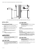

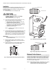


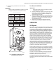


Table Of Contents

Automation and Control Solutions
Honeywell International Inc. Honeywell Limited-Honeywell Limitée
1985 Douglas Drive North 35 Dynamic Drive
Golden Valley, MN 55422 Toronto, Ontario M1V 4Z9
customer.honeywell.com
35 AND 70 LB-IN. NON-SPRING RETURN DIRECT COUPLED ACTUATORS
® U.S. Registered Trademark
© 2006 Honeywell International Inc.
63-2209—9 J.I. Rev. 12-06
CHECKOUT
ML6161, ML6174
To check out ML6161, ML6174 Actuators controlled by
electronic control systems, such as the W7620, override the
control system by programming the controller to open or close
the zone damper, as appropriate.
NOTE: Using a seven-minute actuator results in a longer
response time before noticeable damper movement.
To check out the ML6161 or ML6174:
1. Determine the direction the shaft moves to open the
device (cw or ccw). See Fig. 3.
2. Place 24 volts across the appropriate common cw or
common ccw terminals to energize the actuator. The
actuator should begin to open the device.
3. If the actuator does not run, try switching the 24 volts
across the opposite common cw or ccw terminals to
determine if the device begins to close.
4. If the actuator does not run in either direction, replace
the actuator.
For ML6161 or ML6174 issued with a spdt floating wall
thermostat (for pressure dependent systems), use the
following checkout procedure:
1. Adjust the setpoint of the thermostat to call for cooling.
2. Observe the operation of the actuator; if the device is
closed, it should begin to open.
3. If not, adjust the setpoint of the thermostat higher to
determine if the wiring is correct.
4. If no movement is observed, check for the presence of
24 volts.
5. If using the T641 Thermostat, check that 24 volts are
present between terminals C and Y during a call for
cooling. With proper wiring and 24 volts present, the
actuator should operate correctly.
6. If not, replace the actuator.
ML7161, ML7174
Check input impedance on the actuator with an ohmmeter.
IMPORTANT
Be sure to disconnect all wiring to the actuator before
connecting the ohmmeter.
1. Verify resistance readings are as follows:
• 45K ohms ±5K ohms, across the (+Vdc) and (-)
terminals.
• 536 ohms ±10 ohms, across the (+mA) and (-)
terminals.
2. If the resistance readings are correct, reconnect the
actuator and check for 24 Vac at terminals T and T2.
With the correct power present at T and T2, check the
motion of the shaft/actuator by ramping the setpoint up
and down. This causes the actuator to move from one
limit to the other and back (from fully ccw to fully cw and
back to fully ccw).
NOTE: Remember that the actuator takes 90 seconds
to move from one limit to the other.
3. When the actuator is used with electronic control
systems such as the W7600 Commercial Zone System,
override the control system by programming the
controller to open or close the damper, as appropriate.
4. If the actuator continues to operate incorrectly, check
Table 6 for the proper input signal/actuator drive
relationship at the (+Vdc) and (-) terminals.
5. If the actuator does not operate according to Table 6
values, replace the actuator.
Table 6. Input Signal/Actuator Drive Relationship.
Input Signal Actuator Drive Relationship
1.50 ±0.2 Vdc Actuator drives to extreme ccw position.
2.00 ±0.2 Vdc Actuator remains at ccw position.
3.00 ±0.2 Vdc Actuator leaves ccw position.
10.70 ±0.7 Vdc Actuator drives to extreme cw position.
10.00 ±0.7 Vdc Actuator remains at cw position.
8.50 ±0.6 Vdc Actuator leaves cw position.