
Submittal Sheet

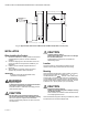

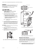


Table Of Contents

35 AND 70 LB-IN. NON-SPRING RETURN DIRECT COUPLED ACTUATORS
9 63-2209—9
4. Insert the screw provided into the hole and fasten
securely.
IMPORTANT
Failure to follow the calibration procedures can result
in improper resistance values at desired stroke.
Fig. 15. ML6161A,C, ML6174A,C with
field-addable potentiometer.
To Calibrate the 200976A,C:
IMPORTANT
Remove the range stop pins and minimum position
setscrews prior to calibration.
1. Drive the actuator fully closed (0°) to fully open (90°) and
back again to the fully closed position. This must be
done to receive the correct resistance readings at the
appropriate degree of stroke.
2. Check the resistance values of the potentiometer with an
ohmmeter at intervals in the stroke while referring to the
table in Fig. 15 and resistance information provided in
the Specifications section.
3. Replace the range stop pins and/or the minimum
position setscrews using the appropriate procedures.
OPERATION
VAV Systems
VAV systems control the temperature within a space by varying
the volume of supply air temperature. The system delivers air
to the space at a fixed temperature. The space thermostat
controls the volume of supply air by modulating the supply air
damper. When full heating and cooling flexibility is required in a
zone, it is handled by the air temperature system, or with
reheat capability in the air terminal units. As individual zones
shut down, a central duct static pressure controller regulates
the total air flow in the system. The fan system is sized to
handle an average peak load, not the sum of the individual
peaks. As each zone peaks at a different time of day, extra air
is borrowed from the off-peak zones. This transfer of air from
low-load to high-load zones occurs only in true VAV systems.
In pressure independent systems, individual zone airflow
sensors maintain the zone air flow rate independent of
fluctuation in the total system pressure. Pressure independent
systems, when used with controllers such as the W7620, can
react faster to changes in air flow demand; therefore, these
systems can use the faster 90-second models.
Pressure dependent systems do not incorporate an individual
zone air flow sensor and depend on a stable system pressure
to maintain flow. These systems require slower actuators such
as the seven-minute models that are typically controlled by
spdt floating wall thermostats.
The T641 is a mercury bulb floating-control type thermostat
designed for use with the seven-minute model on pressure-
dependent systems (see Figures 16 and 17).
The T6984 is an electronic floating-control thermostat
designed for use with the 90-second and seven-minute models
(see Fig. 18).
60
45
45
60
CW
CCW
COM
M10251B
MOTOR
POSITION
RW
RESISTANCE
RB
RESISTANCE
FULLY CW
24V (COM-CW)
FULLY CCW
24V (COM-CCW)
0 OHMS
0 OHMS
500 OR
2000 OHMS
AUXILIARY POTENTIOMETER
MOTOR
ROTATION
AUXILIARY POTENTIOMETER LEADS
RW OHMS RB OHMS
CCW
INCREASE
DECREASE
DECREASE
INCREASE
CW
FIELD-ADDABLE AUXILIARY POTENTIOMETER
500 OR
2000 OHMS
B
R
W