
Submittal Sheet

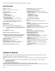


Table Of Contents

35 AND 70 LB-IN. NON-SPRING RETURN DIRECT COUPLED ACTUATORS
7 63-2209—9
1. Determine the direction of the desired closing rotation.
2. Move the actuator to the position fully opposite the
desired closing rotation (if cw closing rotation is desired,
move the actuator to the full ccw position).
3. Determine the correct hole for the setscrew using Fig. 9
and the results of step 1.
CAUTION
Equipment Damage Hazard.
Improper hub positioning or hole selection can
permanently damage the device.
Avoid backdriving the actuator with the setscrew.
4. Remove the red cap from the desired hole. Leave the
other cap in position. The caps ensure that dust and
other impurities do not enter the gear train through
unused holes.
5. Thread the locknut fully onto the 1/4 in. (6 mm) setscrew.
6. Insert the setscrew into the desired hole, turning
clockwise until resistance is encountered or the locknut
contacts the housing.
7. If resistance is met before the setscrew is fully inserted,
stop and review the initial setup procedures as detailed
in steps 1 through 3.
8. Determine the angle of minimum position required for the
application. With the setscrew fully inserted, the
minimum position is 30°. With the setscrew fully out, the
minimum position is 0°.
9. Using the conversion of approximately 1.7 angular
degrees per turn of the setscrew, back the screw out of
the housing and stop slightly short of the calculated
position. This allows the setscrew to be set accurately
while taking air flow measurements.
IMPORTANT
After initiating step 10, the setscrew cannot be turned
into the housing without returning the actuator to the
fully open position (as determined in step 1). The
actuator follows the setscrew without damaging the
housing only when backed out of the housing (turned
ccw).
10. Rotate the actuator to minimum position using the
manual declutch; see Manual Operation (Declutch)
section.
11. With the actuator at minimum position, adjust the
position more accurately using air flow measurements.
NOTES:
1. After each adjustment, ensure the actuator is
completely stopped before proceeding with the
next adjustment.
2. To reduce the minimum position, turn out the
setscrew (ccw). The actuator then drives toward
the closed position.
3. Turning the setscrew in (cw) damages the
actuator housing.
4. If the device is too far closed, return to step 1.
12. When proper air flow is achieved, loosen the locknut
from the setscrew until it contacts the actuator housing,
then turn it an additional 1/8 turn to lock the setscrew in
place.
IMPORTANT
Run an entire check of the operation after completing
this procedure.
Fig. 9. Setscrew location for ML6161 and ML6174.
Wiring
CAUTION
Electrical Shock or Equipment Damage Hazard.
Can shock individuals or short equipment circuitry.
Disconnect all power supplies before installation.
Actuators with auxiliary switches can have more than
one disconnect.
All wiring must comply with local electrical codes, ordinances
and regulations. Voltage and frequency of the transformer
used with the actuator must correspond with the characteristics
of both the power supply and the actuator. Screw terminals are
provided for easy hookup. See Figures 11 through 14 for
typical wiring hookups.
Connecting Wiring to Conduit Cover Actuators
(Fig. 10)
1. Remove the cover from the actuator by lifting the top and
pivoting the cover to the rear of the actuator.
2. Remove the conduit knockouts with a flat-bladed
screwdriver. Discard the knockouts.
3. Install the conduit connector.
4. Run the connecting wire through the conduit connector,
strip the wire ends (if necessary) and connect to the CW,
COM and CCW terminals using Figures 11 through 14,
Figures 16 through 20, or the control manufacturer
instructions.
5. Apply power to the actuator.
6. After operational checkout, replace the cover by
reversing the procedure outlined in step 1.
M10247
60
45
45
60
THIS SETSCREW
CORRESPONDS WITH
CLOSING IN THE
CW DIRECTION
THIS SETSCREW
CORRESPONDS WITH
CLOSING IN THE
CCW DIRECTION