
Submittal Sheet


ML6420, ML7420 NON-SPRING RETURN ELECTRIC LINEAR VALVE ACTUATORS
63-2533—2 6
Auxiliary Potentiometers
The 43191679 Auxiliary Potentiometers can be used as
feedback potentiometers and to provide remote indication of
valve position. See the Installation Instructions packed with
the potentiometers.
Auxiliary Switches
The 43191680 Dual Auxiliary Switch can be used on both the
ML6420 and ML7420 Electric Linear Valve Actuators. Switching
points are adjustable over the full length of the actuator stroke;
for example, the switch can be used to switch pumps or to
provide remote indication of any stroke position. See the
Installation Instructions packed with the auxiliary switch.
CAUTION
Equipment Damage Hazard.
Improper voltage damages the auxiliary switch
beyond repair.
Use the 43191680 Dual Auxiliary Switch only with
24 Vac applications.
OPERATION
General
In the actuator, the drive of a synchronous motor is converted
into the linear motion of the actuator stem by using a spur
gear transmission. A button retainer clip connects the actuator
stem to the valve stem.
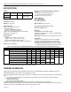
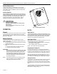
Manual Operation
The ML6420 and ML7420 are equipped with a manual
operator knob (see Fig. 14) to open or close the valve in the
event of power failure:
1. Turn off or disconnect the power supply before manually
operating the actuator.
2. Push down on the manual operator knob and turn the
knob:
a. Counterclockwise to drive the stem downward.
b. Clockwise to draw the stem upward.
IMPORTANT
Manual operation allows very high closing force that
can jam the actuator spindle, exceed the force switch
ratings, and stop the motor. After a manual valve
close-off operation, release the spindle one turn by
turning the manual operator knob. This will ensure
automatic disengagement of the manual operator
upon power resumption.
NOTE: If the manual operator knob is not pushed in while
turned, it will rotate only a short distance before
disengaging without power resumption.
Fig. 14. Manual operator knob.
ML7420
Signal Input (+)
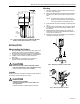
The analog input signal (+) range is set at the factory to 0 to
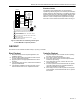
10 Vdc. Changing the position of the W2 selector plug sets the
range to 2 through 10 Vdc. Selector plugs W1, W2, and W3
are positioned on the back side of the printed circuit board.
See Fig. 12 for location of the selector plugs.
Signal Input Failure
Using selector plug W1, the actuator can be set to run to one
of three positions in event of a signal failure:
• 0% Actuator position corresponds with 0 or 2 Vdc signal.
• 50% Actuator in mid-position.
• 100% Actuator position according to 10 Vdc signal.
NOTE: W1 is factory set at the mid-position.
Output Signal Feedback (F)
An analog output signal (2 to 10 Vdc) that represents the
actual actuator stem position is available at terminal F. It can
be used for remote indication of the stem position. When the
actuator stem is fully downward, the output signal is 10 Vdc.
When the valve stem is up, the output signal is 0 or 2 Vdc.
The output of the signal does not change when the action of
the actuator is reversed using W3. See Direction of Action.
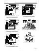
Actuator Override
To override the control signal (for freeze protection or similar
applications), connect the 24 Vac common (T2) to either
terminal O1 or O2. Connecting to terminal O1 fully extends
the actuator stem. Connecting to O2 fully retracts the actuator
stem.
The control signal (+) is ignored when the override signal is
applied to terminal O1 or O2. This override can be achieved
with a switch or a relay. See Fig. 15.
M664
0