
Install Instructions
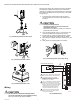
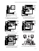
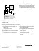
Table Of Contents

ML6420, ML7420 NON-SPRING RETURN ELECTRIC LINEAR VALVE ACTUATORS
Automation and Control Solutions
Honeywell International Inc.
1985 Douglas Drive North
Golden Valley, MN 55422
customer.honeywell.com
® U.S. Registered Trademark
© 2011 Honeywell International Inc.
63-2533—03 M.S. Rev. 07-11
Printed in U.S.A.
Fig. 15. Connections for overriding control signal
to drive ML7420 to a specific position.
Direction of Action (ML7420/25 only)
The direction of the actuator action can be changed using the
pushbutton and LED, which is factory set so that the actuator
drives the valve stem down on increasing signal and draws
the valve stem up on decreasing signal. With the valve stem
up, the output signal from the feedback (F) function is either 0
or 2 Vdc. The output of the signal does not change when W3
is used to reverse the actuator action. See Fig. 12.
CHECKOUT
The actuator can be checked out either directly or by using a controller.
Direct Checkout
1. Mount the actuator for the required application; see
Installation section.
2. Check the valve position and make sure that 24 Vac is
correctly applied to the actuator.
3. Apply the power to the appropriate leadwires to move
the valve.
4. If the actuator does not move, make sure the actuator is
properly installed/wired.
5. If the actuator installation and wiring are both correct
and the actuator does not run, replace the actuator.
Controller Checkout
1. Adjust the setpoint of the controller to call for opening
the valve. Observe the actuator.
2. If the valve is closed, it should begin to open.
3. If the valve remains closed, move the setpoint further
toward the open setting.
4. If the valve does not move, check for 24 Vac in the
actuator power input.
5. If 24 Vac is present and the actuator does not operate,
check the voltage across the controller leadwires to
determine if the device is miswired.
6. If the wiring is correct, 24 Vac is present on the power
input terminals, and the actuator does not run, replace
the actuator.
POWER SUPPLY. PROVIDE DISCONNECT MEANS
AND OVERLOAD PROTECTION AS REQUIRED.
F
+
0-10Vdc OR 2-10 Vdc CONTROL SIGNAL. SEE SIGNAL
INPUT (+) SECTION.
SEE OVERRIDE SECTION FOR DETAILS ON
OVERRIDE OPERATION.
2-10 Vdc FEEDBACK SIGNAL. SEE OUTPUT SIGNAL
FEEDBACK SECTION.
ML7420
WIRING
STRIP
F
+
–
T2
T1
O1
O2
1
3
4
2
INPUT
(FEEDBACK)
OUTPUT
3
2
SP3T
OVERRIDE
SWITCH
4
1
L1
(HOT)
L2
–
M17429