
Submittal Sheet


ML7984 VaLVe actuator
Automation and Control Solutions
Honeywell International Inc.
1985 Douglas Drive North
Golden Valley, MN 55422
Honeywell Limited-Honeywell Limitée
35 Dynamic Drive
Toronto, Ontario M1V 4Z9
customer.honeywell.com
® U.S. Registered Trademark
© 2011 Honeywell International Inc.
95C-10753—02 M.S. Rev. 05-11
Printed in U.S.A.
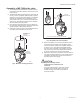
OPERATION
WARNING
Electrical Shock Hazard.
Can cause severe injury, death or property
damage.
Disconnect power supply before beginning
wiring or making wiring connections to prevent
electrical shock or equipment damage.
Make certain that the voltage and frequency of
the power supply correspond to the rating of the
device.
CAUTION
Equipment Damage Hazard.
Installer must be a trained service
technician.
Do not electrically operate the ML7984 before
assembly to the valve because damage not ap-
parent to the installer may occur.
Do not connect 24 Vac between any signal input
terminals. Device failure will result.
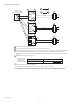
The recommended valve actuator power source is a class
2, 24V transformer or 28Vdc across terminals T5 &T6 (See
Fig7-10). The internal circuitry provides dc power for the elec-
tronic sensing and drive motor circuits. The sensing circuits
respond to the signal across the input terminals based on the
conguration DIP switches setting. When correctly connected
to the actuator, control signal between signal input terminals
is compared to similar voltage across the actuator feedback
potentiometer. When these voltages are equal, the drive mo-
tor and drive shaft are stationary. As long as the value of con-
trolled medium remains at the controller setpoint, the circuit is
in balance, and the actuator does not run. When the value of
the controlled medium changes, the controller output voltage
is changed causing reference voltages in the circuit to be out
of balance. As the actuator moves in the direction to correct
the medium change, the feedback potentiometer also moves
to rebalance the circuit, and stop the actuator. At the end of
the valve stroke, the actuator continues to drive and gradually
develops the necessary force for positive valve close-off. The
actuator motor stops automatically when the motor current
reaches the predetermined current & force level.
CHECKOUT
1. Make sure the valve stem is completely screwed into
the actuator drive shaft with no threads showing.
2. Make sure the valve stem is locked in place with the set
screw.
3. Make sure the Conguration DIP switches are set
correctly.
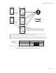
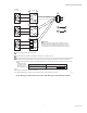
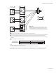
4. With 24Vac or 28Vdc power source connected to T5
& T6, actuator operation can be veried by connecting
appropriate control signal (Series 70/90 ) from control-
ler to the signal input terminals (Fig 7-10). For direct
acting: A modulating action can be obtained simply by
increasing the control signal. The actuator will travel
from a fully closed position (Stem down) to a fully open
position ( Stem up ). On signal failure (disconnected
/ no signal), actuator defaults to closed position. For
reverse acting: Decreasing controller signal will drive
actuator from fully closed (Stem down) to a fully open
position (Stem up). On signal failure (disconnect/no
signal), actuator defaults to open position.
5. Operate the system (valve, actuator and controller) for
several cycles to ensure proper installation.
6. When checkout is completed, return the controller to
the desired setting.
NOTE: Device will ignore any input changes until it has
completed its repositioning relative to the initial sig-
nal input.
GENERAL NOTES
1. For correct valve operation, the ML7984 must be eld
conFigd with the DIP switches which are located beside
the terminal block, see wiring diagrams for details. Turn
power off before setting the DIP switches .
2. There is a short delay in actuator response upon every
signal change. It is to screen any unwanted incoming
signals.
3. For proper operation, voltage on the T5 & T6 must not
be less than 22Vac or 24Vdc during running or force
generating stages.