
Submittal Sheet


ML7984 VaLVe actuator
3
95C-10753—02
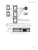
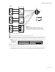
Assembly of ML7984 to the valve:
1. The drive shaft of the ML7984 has a threaded hole to
link with the valve stem. Slide the yoke over the valve
bonnet (Fig 4)
2. Thread the ML7984 drive shaft onto the valve stem all
the way, until it is completely attached (with no thread-
sshowing), by turning the valve actuator in a clockwise
direction, as viewed from above (depending on the
valve models, use a pin or wrench to keep valve stem
from turning). Note that the valve actuator is shipped
with drive shaft in the mid-position.
3. Care should be exercised when using the TOOLS on
the valve stem during tightening. (Fig 4) DO NOT dam-
age the threads or other parts of the stem.
4. Orient the conduit hole to the most desirable direction,
then tighten the LOCKNUTS on the U-bolt.
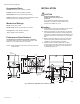
MINIMUM
MOUNTING
CLEARANCE
12
(305)
4 (102) FOR
ACTUATORS WITH
AUXILIARY
SWITCHES 3 (76)
M32558
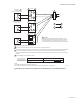
Fig 2. Minimum mounting clearance.
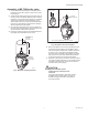
ASSEMBLY OF THE
POSITION INDICATOR.
POSITION INDICATOR
(PLASTIC DISK)
VALVE
STEM
NOTE: DO NOT DAMAGE ANY PART OF THE STEM
REMOVE
STEM BUTTON
M32559
Fig 3. Preparation for valve assembly.
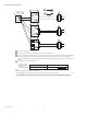
5. Remove the plastic cover from the ML7984 by loosen-
ing the two screws located on the top (Note: These
screws are captive. Rotate three complete revolutions
to remove cover ). Drop either Slot Headed or Allen
Hex type of set screw (both are included in the plastic
bag ) into the top of the shaft, slotted/ Hexed side up.
Or use the set screw from the valve stem button.
6. Depends on which type of set screw was used, with a 5
mm (3/16”) Slotted screwdriver or 1/8”x 6” Allen wrench
(included in the plastic bag), tighten the set screw to
lockvalve stem in place (Fig 6).
CAUTION
Equipment Damage Hazard.
Installer must be a trained service
technician.
For proper valve operation, valve stem must be
threaded into the actuator all the way (with no
threads showing) and locked in place with the
set screw provided.