
Submittal Sheet
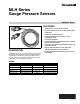

Table Of Contents

MLH SERIES GAUGE PRESSURE SENSORS
62-0296—03 2
SPECIFICATIONS
(All specifications are measured at 25°C (77°F) and at rated
excitation unless otherwise specified.)
Operating, storage and compensated temperature range:
-40° C to 125° C (-40° F to 257° F)
Proof Pressure:
3X Working Pressure Range (50-500 psi)
2X Working Pressure Range (1000 psi)
Burst Pressure:
10X Working Pressure Range
Dimensions:
See Fig. 1 and 2.
Housing Material:
Black plastic — Amodel AS-4133 HS - PPA
Material in contact with media:
Stainless steel 304L and Haynes 214 alloy
Excitation:
9.5Vdc to 30Vdc
Signal Output:
4mA to 20ma
Zero Output:
4.0mA
Full Scale Span (FSS):
16mA (4 to 20mA)
Supply rejection ratio:
90db
Termination:
Cable (3 meter)
Red Lead (Excitation)
White Lead (Output Signal)
Shock:
50 g peak [5 ms], 100 g peak [11 ms]
Vibration:
MIL- STD- 810C. Figure 514.2-5, Curve AK, Table 514.2-V,
Random Vibration Test [overall g rms = 20.7 min.]
Performance
1
Includes pressure non-linearity (BFSL), pressure hysteresis,
and non-repeatability. Thermal errors are not included.
2
Includes zero error, span error, thermal effect on zero, ther-
mal effect on span, thermal hysteresis, pressure-non-linear-
ity, pressure hysteresis, and non-repeatability.
Fig. 1. MLH050PSCDJ1235/MLH150PSCDJ1236/
MLH300PSCDJ1237 dimensions in in. (mm).
Fig. 2. MLH01KPSCDJ1241/MLH500PSCDJ1240
dimensions in in. (mm).
WARNING
Personal Injury
Do not use these products as safety or emergency
stop devices or in any other application where failure
of the product could result in personal injury.
Failure to comply with these instructions could result in
death or serious injury.
General Information
All gauge sensors are vented to the atmosphere through a
case vent hole that is protected with a vapor inhibiting
material.
Pressure Overloads
CAUTION
Product Damage
Do not exceed the pressure overload rating.
Failure to comply with these instructions may result in
reduced life or electrical failure.
The MLH series pressure sensors will withstand high
overloads; however, if the proof rating is exceeded, the life of
the sensor may be reduced and electrical failure may occur.
Both static and dynamic overloads must be considered,
particularly in hydraulic system applications. Hydraulic
pressure fluctuations can have very high and very fast peak
pressures, as in a water hammer effect.
An oscilloscope is recommended for determining if high-
pressure transients exist in a system. If system pressure
pulses are expected, choose a sensor with a pressure rating
high enough to allow continuous operation at the highest
expected pressure spikes.
Parameter Specification
Response Time <2 ms
Accuracy
1
<100 psi ±0.50% FSS
≥100 psi ±0.25% FSS
Total error band
2
<300 psig (-40°C to 125°C [-40°F to 257°F]) ±3% FSS
≥300 psig (>65°C to 125°C [>149°F to 257°F]) ±2% FSS
1 (25)
57/64 (23)
31/64
(12)
45/64 (18)
7/16 (11)
5/32 (4)
1-27/32 (47)
#8-32 ROLLED
THREADS
THRU
ALL Ø 9/64 (4)
RED
WHITE
119-51/64 (3043)
35/64
(14)
Ø 3/64 (1)
M29496
#1/4-18 NPT
M29495
1-3/4 (44)
119-45/64 (3040)
7-16-20 UNF-2B
RED
WHITE
Ø 3/64 (1)
45/64 (18)
7/16 (11)
5/32 (4)
35/64 (14)
51/64 (20)
5/8 (16)