
Install Instructions


MP909E
UL Listed Damper Actuator
BEFORE INSTALLATION
The MP909E UL Listed Pneumatic Damper Actuator is used
for control of Leakage Rated (Smoke) Dampers, classified
under Underwriters Laboratories Standard 555S, for use in
smoke control systems. The MP909 is a piston-type, rolling-
diaphragm operated actuator and can be mounted in any
position and installed either externally or internally.
The UL listing of the actuator and the damper classification
apply only when Listed Honeywell Actuators are installed on
Honeywell D640SD, D641SD, D644SD, or D645SD Series
Dampers as specified in the installation instructions shipped
with the devices.
All installations must also comply with the requirements of
NFPA 90A, National Fire Protection Standard for the
Installation of Air Conditioning Systems.
Table 1 lists the only MP909 Actuators approved for use with
UL Classified Leakage Rated (Smoke) Dampers.
Table 1. Damper Actuators for Leakage Rated Dampers.
Actuator
Model
Spring Range
psi (kPa) Mounting Bracket
MP909E1422 5-10 (34-69) Internal/
Normally
Open
Trunnion
MP909E1414 5-10 (34-69) Internal/
Normally
Closed
Trunnion
MP909E1034 5-10 (34-69) External 90° Fixed
MP909E1364 5-10 (34-69) External Trunnion
Mainline pressure limits:
— 15 psi minimum
— 25 psi maximum
Tools needed:
1. 7/16-inch box end wrench
2. 1/8-inch Allen wrench
3. Squeeze bulb
INSTALLATION INSTRUCTIONS
INSTALLATION
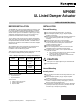
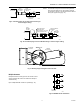
External Mounting
For external mounting dimensions, see Figure 1.
Check faceplate position (Fig. 2). Adjust faceplate
position if necessary.
Determine the damper drive axle direction of rotation to
the normal position (position with 0 psi applied to
actuator).
Rotate damper drive axle to normal position.
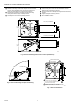
Locate proper shaft hole (Fig. 3) over damper shaft.
Arrow on bracket surrounding hole should match
rotation determined in Step 3.
Position mounting bracket.
Secure mounting bracket. Use four of the 10 holes
available in bracket and drill screws provided.
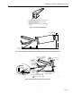
To provide close-off force, use a squeeze bulb and
stroke the actuator:
a. For normally open dampers, fully extend actuator
shaft then retract 1/2-inch (13 mm).
b. For normally closed dampers, extend actuator
shaft 1/2-inch (13 mm).
CAUTION
See Figure 4 for proper tightening of crankarm bolts.
Go to PIPING section.
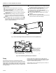
Internal Mounting
Normally Closed
For normally closed internal mounting dimensions, see
Figure 5.
Check faceplate position (Fig. 6). Adjust faceplate
position if necessary.
Use a 1/8-inch Allen wrench to loosen mounting set
screws on damper mounting clamp (Fig. 6) one turn.
Remove and discard shipping stop.
Locate factory-installed drive ear on damper. (Mounted
per Damper Ordering Instructions.) Actuators must be
mounted only in this (these) position(s)
Copyright © 1996 Honeywell Inc. • All Rights Reserved
11-95 UL
95-6076