
Install Instructions
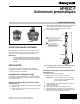

MP953C-F PNEUMATIC ACTUATORS
Valve Actuator Installation
MF953C,E Mounting
CAUTION
Equipment Damage Hazard.
Moving locking slide with screwdriver or similar
tool can damage it beyond repair.
Use your fingers to move the locking slide.
1.
Loosen both setscrews at base of actuator (see Fig. 5).
2.
Position stem locking slide so that the large hole in the
slide can be seen when viewed from bottom of actuator.
3.
Position actuator on valve bonnet.
IMPORTANT
Do not tighten mounting setscrews in actuator base.
4.
Slowly apply air pressure to stroke actuator. While
applying pressure, rotate actuator until stem button
drops into parallel locking tabs.
5.
Secure stem button by pulling locking slide with fingers.
6.
Remove air pressure.
7.
Ensure actuator is properly engaged to valve stem by
trying to lift actuator from valve stem.
8.
Once actuator is properly fastened:
a. Return actuator to its original position on the valve.
b. Tighten actuator to valve with bonnet setscrews in
actuator base.
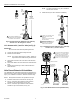
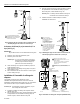
Fig. 5. MP953C,E Actuator Connected to Stem Button.
POSITIVE
POSITIONER
(MP953E
ONLY)
STEM
BUTTON
STEM
LOCKING
SLIDE
M17342
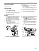
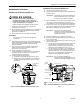
MP953D,F Mounting
1.
Pull valve stem up.
2.
Remove stem button connector (Fig. 6) from actuator
and attach to stem button.
NOTE: When properly installed, locking ring fits over neck
of stem button locking both components together.
3.
Place actuator on valve without pushing stem down. If
the stem is pushed down, the connector threaded shank
will not reach the actuator.
4.
Turn connector screw slot counterclockwise
to
back out stem button. (It is also possible to hold the
screw and spin the actuator clockwise
.)
NOTE: On straight-through valves, actuator should
now be flush with valve bonnet shoulder.
5.
Push actuator onto valve bonnet.
6.
Hold actuator firmly in place and tighten both setscrews.
7.
Load stem by turning stem button connector
clockwise .
a. Straight-through valve: Turn connector screw until a
clearance of approximately 1/8 in. (3 mm) exists
between spring cup and actuator base. (See Fig. 6,
clearance A.)
b. Three-way valve: Clearance is required at both ends
of the stroke to permit proper close-off. (See Fig. 6,
clearances A and B.) Both clearances should be the
same.
NOTE: If there is no air on the actuator, clearance A
will require adjustment when air is available.
M17343
CONNECTOR
SCREW
SLOT
REVERSED THREADS
STEM
BUTTON
CONNECTOR
CLEARANCE B
CLEARANCE A
1
1
MEASURED WHEN SPRING IS COMPRESSED.
Fig. 6. MP953D,F Actuator Connected to Stem Button.
3 95-6044EF