MS4980 Area Imaging Scanner Installation and User's Guide
Disclaimer Honeywell International Inc. (“HII”) reserves the right to make changes in specifications and other information contained in this document without prior notice, and the reader should in all cases consult HII to determine whether any such changes have been made. The information in this publication does not represent a commitment on the part of HII.
TABLE OF CONTENTS Introduction Product Overview ............................................................................................. 1 Scanner and Accessories................................................................................. 2 Scanner Components....................................................................................... 3 Cable Installation.............................................................................................. 4 Cable Removal.........................
TABLE OF CONTENTS Scanner and Cable Terminations Scanner Pinout............................................................................................... 28 Cable Connector Configurations .................................................................... 30 Limited Warranty ................................................................................................ 32 Regulatory Compliance Safety .....................................................................................................
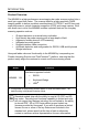
INTRODUCTION Product Overview The MS4980 is a high performance area imaging bar code scanner packed into a small yet rugged form factor. The scanner features a high-resolution CMOS imaging sensor to deliver excellent omnidirectional 1D, PDF417 and 2D bar code scan performance, optical character recognition (OCR) and image capture.
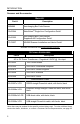
INTRODUCTION Scanner and Accessories BASIC KIT Part # Description MS4980 Area Imaging Bar Code Scanner 00-02544 MetroSelect® Single-Line Configuration Guide* 00-05252 Area Imaging Bar Code Scanner Supplemental Configuration Guide* 70-79037 MS4980 Scanner Installation and User’s Guide* *Available for download from www.honeywell.com/aidc OPTIONAL ACCESSORIES Part # Description AC to DC Power Transformer – Regulated 5.2VDC @ 1A output.
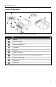
INTRODUCTION Scanner Components Figure 1. Scanner Components Item No.
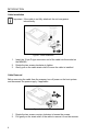
INTRODUCTION Cable Installation Important: If the cable is not fully attached, the unit may power intermittently. Figure 2. Cable Installation 1. 2. 3. Insert the 15-pin D-type connector end of the cable into the socket on the MS4980. Rotate the two screws clockwise to tighten. Gently pull on the cable strain relief to insure the cable is installed. Cable Removal Before removing the cable from the scanner, turn off power on the host system and disconnect the power supply, if applicable. Figure 3.
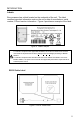
INTRODUCTION Labels Every scanner has a label located on the underside of the unit. The label contains important information such as the unit’s date of manufacture, serial number, CE and caution information. Figure 4 provides an example of the label. Figure 4 . Label Example Caution: To maintain compliance with applicable standards, all circuits connected to the scanner must meet the requirements for SELV (Safety Extra Low Voltage) according to EN/IEC 60950-1. To maintain compliance with standard CSA-C22.
INSTALLATION RS232 1. Turn off the host device. 2. Plug the 15-pin socket end of the cable into the 15-pin D-Type connector on the MS4980 (see page 4). 3. Connect the 9-pin D-type connector of the communication cable to the proper COM port of the host device. 4. Plug the power supply into the power jack on the PowerLink cable. Check the AC input requirements of the power supply to verify the voltage matches the AC outlet. The outlet must be located near the equipment and be easily accessible.
INSTALLATION Keyboard Wedge 1. Turn off the host device. 2. Plug the 15-pin socket end of the cable into the 15-pin D-Type connector on the MS4980 (see page 4). 3. Disconnect the keyboard from the host device. 4. Connect the “Y” ends of the communication cable to the keyboard and keyboard port on the host device. If necessary, use the male/female adapter cable supplied with the scanner for proper connections. 5. Plug the power supply into the power jack on the PowerLink cable.
INSTALLATION USB (Powered by the Host Device) 1. Turn off the host device. 2. Plug the 15-pin socket end of the USB cable into the 15-pin D-Type connector on the MS4980 (see page 4). 3. Plug the USB end of the cable into the host’s USB port. 4. Turn on the host device. 5. The MS4980 will start to initialize. The white and blue LED will alternately fade on and off for approximately three seconds.
INSTALLATION USB (Powered by External Power Supply) 1. Turn off the host device. 2. Plug the 15-pin socket end of the cable into the 15-pin D-Type connector on the MS4980 (see page 4). 3. Plug the USB end of the cable into the host’s USB port. 4. Plug the power supply into the power jack on the PowerLink cable. Check the AC input requirements of the power supply to verify the voltage matches the AC outlet. The outlet must be located near the equipment and be easily accessible. 5.
MOUNTING SPECIFICATIONS The MS4980 has three M3 x 0.5 mm threaded inserts on the bottom of the scanner for mounting with screws. Figure 10.
MODES OF OPERATION The MS4980 supports two standard modes of operation for scanning bar codes, automatic activation and manual activation scanning. Scanning while in the automatic activation mode can occur in either one of two configurable options, pass-through or presentation. Both the pass-through and the presentation With the default configuration, the scanner options are enabled by default.
MODES OF OPERATION Manual Activation • Decodes ALL 1D, PDF and 2D matrix codes • Scanning Method: 1. Press the button one time to activate linear targeting. 2. Align the linear targeting line over the desired bar code. When scanning 1D programming bar codes, the bar code must be presented to the scanner in the correct orientation, see Figure 11. Figure 11. 1D Programming Bar Code Orientation PDF and 2D matrix codes may be presented in any orientation. 3.
INDICATORS Audible When the MS4980 is in operation, it provides audible feedback. These sounds indicate the status of the scanner. Eight settings are available for the tone of the beep (normal, six alternate tones and no tone). To change the tone, refer to the MetroSelect Single-Line Configuration Guide, MLPN 00-02544 or MetroSet2’s help files. One Beep When the scanner successfully reads a bar code the unit will beep once and the white LED will flash once indicating data has been transmitted successfully.
INDICATORS Visual The scanner has blue and white LED indicators on either side of the button on the top of the unit. When the scanner is on, the intensity of the LED and the flashing or stationary activity of the LEDs, indicates the status of the current scan and the diagnostic scanner. Figure 12. No LEDs are Illuminated The LEDs will not be illuminated if the scanner is not receiving power from the host or transformer. Steady Low Intensity Blue The scanner is in stand-by mode.
INDICATORS Failure Modes Long Razzberry Tone – During Power Up Failed to initialize or configure the scanner. If the scanner does not respond after reconfiguration, return the scanner for repair. Short Razzberry Tone – During Scanning An Invalid bar code has been scanned when in configuration mode.
FIELD OF VIEW Figure 13. MS4980 Field of View Specifications are subject to can without notice.
DEPTH OF FIELD MINIMUM BAR CODE ELEMENT WIDTH 1D PDF A B C D E F mm .132 .190 .264 .330 .190 .381 mils 5.2 7.5 10.4 13 7.5 15 Figure 14. Depth of Field Standard models ship with the ability to read all 1D, PDF and 2D bar codes. Decoding and functional capability is limited and units will not support key features including, but not limited to, the ability to decode PDF, 2D or OCR fonts without proper limited use licenses provided by Honeywell.
IR ACTIVATION RANGE The MS4980 scanner has a built in object detection sensor that instantly turns on the scanner when an object is presented within the scanner’s IR activation area. Figure 15. IR Activation Area Specifications are subject to can without notice.
TROUBLESHOOTING GUIDE The following guide is for reference purposes only. Contact a customer service representative to preserve the limited warranty terms, see page 39. All Interfaces Symptoms Possible Causes Solution No power is being supplied to the scanner. Check transformer, outlet and power strip. Make sure the cable is plugged into the scanner. No power is being supplied to the scanner from the host. Some host systems cannot supply enough current to power the MS4980.
TROUBLESHOOTING GUIDE Symptoms Possible Causes Solution The unit powers The beeper is up, but does not disabled and no tone beep when bar is selected. code is scanned. Enable the beeper and select a tone. The unit powers up, but does not scan and/or beep. The bar code symbology trying to be scanned is not enabled. UPC/EAN, Code 39, interleaved 2 of 5, Code 93, Code 128, Codabar and PDF are enabled by default. Verify that the type of bar code being read has been selected.
TROUBLESHOOTING GUIDE Symptoms The unit beeps at some bar codes and NOT for others of the same bar code symbology. The unit scans the bar code but there is no data. Possible Causes Solution The bar code may have been printed incorrectly. Check if it is a check digit/character/or border problem. The scanner is not configured correctly for this type of bar code. Check if check digits are set properly. The minimum symbol length setting does not work with the bar code.
TROUBLESHOOTING GUIDE Symptoms The unit scans but the data is not correct. Possible Causes The scanner and host may not be configured for the same interface parameters. Solution Check that the scanner and the host are configured for the same interface parameters. The following item is only relevant for an RS232 interface. The unit powers up OK and scans OK but does not communicate properly with the host. The com port at the host is not working or not configured properly.
DESIGN SPECIFICATIONS MS4980 DESIGN SPECIFICATIONS OPERATIONAL Light Source: Pulse Duration: Maximum Output of LED: Depth of Scan Field: LED 645 nm ± 7.5 nm Up to 4 mS (Default) 2.63 mW 40 mm – 300 mm (1.57" – 11.8") for 0.33 mm (13 mil) 40 mm x 30 mm (1.57" x 1.18") @ 40mm (1.57") from Face Field of View: 250 mm x 187.5 mm (9.84" x 7.38") @ 300 mm (11.8") from Face 1D 0.127 mm (5 mil) 2D 0.19 mm (7.
DESIGN SPECIFICATIONS MS4980 DESIGN SPECIFICATIONS ELECTRICAL Input Voltage: 5.2 VDC ± 0.25V Power: Current: ¡ DC Transformers: RS232, USB w/Power Jack, Keyboard Wedge USB Host Powered Peak¡ 2.1 W (Typical) 1.9 W (Typical) Operating 1.7 W (Typical) 1.7 W (Typical) Idle 1.2 W (Typical) 1.2 W (Typical) Peak¡ 398 mA (Typical) 360 mA (Typical) Operating 331 mA (Typical) 317 mA (Typical) Idle 230 mA (Typical) 230 mA (Typical) Peak Values of at least 1 ms in width. Class II: 5.
Applications and Protocols The model number on each scanner includes the scanner number. VERSION IDENTIFIER SCANNER COMMUNICATION PROTOCOL(S) Interfaces supported include: MS4980 124 • RS232 (TXD, RXD, RTS, CTS) • Keyboard Wedge • USB USB is configurable for Keyboard Emulation Mode, Bi-Directional Serial Emulation Mode or IBM OEM. The default USB setting is Keyboard Emulation Mode. The following are the most important selectable options specific to the keyboard wedge.
CONFIGURATION MODES The MS4980 has three modes of configuration. • Bar Codes The MS4980 can be configured by scanning the bar codes included in the MetroSelect Single-Line Configuration Guide (MLPN 00-02544) or the Area Imaging Supplemental Configuration Guide (MLPN 00-05252) shipped with the area imager. These manuals can also be downloaded FREE from www.honeywell.com/aidc.
UPGRADING THE FIRMWARE The MS4980 scanner is part of Honeywell’s line of scanners with flash upgradeable firmware. The upgrade process requires a new firmware file supplied to the customer by a customer service representative and the MetroSet2 software . A personal computer running Windows 95 or greater with an available RS232 serial or USB port is required to complete the upgrade. Do not use the standard cable supplied with Keyboard Wedge MS4980 interface kits for firmware upgrades.
SCANNER AND CABLE TERMINATIONS Figure 16.
SCANNER AND CABLE TERMINATIONS Figure 17.
SCANNER AND CABLE TERMINATIONS Cable Connector Configurations (Host End) RS232 PowerLink Cable MLPN 52-52557x-3 Pin Function 1 Shield Ground 2 RS232 Transmit Output 3 RS232 Receive Input 4 No Connect 5 Power/Signal Ground 6 Reserved 7 CTS Input 8 RTS Output 9 5VDC Host 9-Pin D-Type Connector USB PowerLink Cable MLPN 52-52559x-3 Pin 1 2 3 4 Shield Function PC +5V DD+ Ground Shield Non-Locking, Type A USB Direct Cable 52-52559x-N-3 MLPN Pin 1 2 3 4 30 Function +5VDC/Power DD+ Gro
SCANNER AND CABLE TERMINATIONS Cable Connector Configurations Keyboard Wedge PowerLink Cable MLPN 52-52558x -3 Pin 1 2 3 4 5 Pin 1 2 3 4 5 6 Function Keyboard Clock Keyboard Data No Connect Power Ground +5 Volts DC Function PC Data No Connect Power Ground +5 Volts DC PC Clock No Connect 5-Pin DIN, Female 6-Pin DIN, Male An adapter cable with a 5-pin DIN male connector on one end and a 6-pin mini DIN female connector on the other will be supplied.
LIMITED WARRANTY Honeywell International Inc. ("HII") warrants its products and optional accessories (“Accessories”) to be free from defects in materials and workmanship and to conform to HII’s published specifications applicable to the products purchased at the time of shipment.
REGULATORY COMPLIANCE Safety ITE Equipment IEC 60950-1, EN 60950-1 LED Class 1 LED Product: IEC 60825-1:1993+A1+A2, EN 60825-1:1994+A1+A2 Caution Use of controls or adjustments or performance of procedures other than those specified herein may result in hazardous radiation exposure. Under no circumstances should the customer attempt to service the LED scanner. Never attempt to look at the LED beam, even if the scanner appears to be nonfunctional.
REGULATORY COMPLIANCE EMC Emissions FCC Part 15, ICES-003, CISPR 22, EN 55022 Immunity CISPR 24, EN 55024 NOTE: Immunity performance is not guaranteed for scanner cables greater than 3 meters in length when fully extended. Changes or modifications not expressly approved by the party responsible for compliance could void the user’s authority to operate the equipment. Class A Devices The following is applicable when the scanner cable is greater in length than 3 meters (9.
REGULATORY COMPLIANCE EMC Changes or modifications not expressly approved by the party responsible for compliance could void the user’s authority to operate the equipment. Standard Europeo Attenzione Questo e’ un prodotto di classe A. Se usato in vicinanza di residenze private potrebbe causare interferenze radio che potrebbero richiedere all’utilizzatore opportune misure. Attention Ce produit est de classe “A”. Dans un environnement domestique, ce produit peut être la cause d’interférences radio.
PATENTS This Honeywell product may be covered by, but not limited to, one or more of the following US Patents: US Patent No.
INDEX A AC ...........................................2, 24 accessories ...................................2 adapter ....................................2, 31 audible indicator .............. 11–15, 27 B bar code .................... 17, 19–22, 26 beep .................... 11–15, 19–22, 27 blue LED...................... 3, 11–15, 27 button ....................................12, 27 C cable..............................................3 adapter.......................................2 communication...........
INDEX P operational............................... 23 parts ..............................................3 patents.........................................36 pinouts........... 28–29, 28–29, 30–31 power ................................ 2, 24, 27 protocols......................................25 T R U razz ........................... 11–15, 19–22 red LED .........................................3 repair ...........................................32 RMA ............................................
CONTACT INFORMATION The Americas (TA) Germany USA Tel: 49-89-89019-0 Fax: 49-89-89019-200 Email: info@de.metrologic.com Tel: 866.460.8033 (Customer Service) 888.633.3762 (Technical Support) 856.228.8100 (Corporate) Fax: 856.228.6673 (Sales) 856.228.1879 (Marketing) 856.228.0653 (Legal/Finance) Italy Tel: +39 0 51 6511978 Fax: +39 0 51 6521337 Email: info@it.metrologic.com Brazil Poland Tel: 55.11.5185.8222 Fax: 55.11.5185.8225 Email: info@br.metrologic.
PRODUCT SERVICE AND REPAIR North America Tel: 866.460.8033 Fax: 856.228.6673 (Sales) Email: info@metrologic.com 40 Suzhou Sales Office Tel: 86-512-67622550 Fax: 86-512-67622560 Email: info@cn.metrologic.
NOTES
NOTES
February 2009 70 - 79037B