
Overview of Primary Product
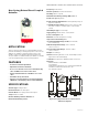
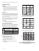
Table Of Contents
VBN THREADED CONTROL BALL VALVES AND ACTUATORS
15 63-4378—08
Cavitation Limits
To prevent cavitation (the formation and collapse of steam
bubbles), a conservative rule-of-thumb is to limit the
pressure drop across the control valve to:
ΔP < 1/2 x (absolute head pressure (psia) - water
vapor pressure (psia))
Water vapor pressure increases with fluid temperature,
reducing the allowable pressure drop, but even chilled
water can cavitate with sufficient pressure differential.
Typical pressure drop across a control valve is in the range
of 3 to 5 psid. Two-position valves will typically show 0.5
psid pressure drop. Design coil flow should be limited by a
balancing valve.
TYPICAL SPECIFICATIONS
Valve Actuator
Direct coupled actuator shall accept analog modulating
[(0)2-10 Vdc], floating (tri-state), or two-position signal as
indicated in the control sequence. Actuators shall be by
Honeywell. Actuator shall provide minimum torque
required for full valve shutoff position. Wiring terminals
shall be provided for installation to control signal and
power wiring.
Actuator shall be available with housing suitable for
outdoor installation.
Accessories Identification tags shall be available for all
valves; tags shall be indelibly marked with C
V
, model
number, and tag location.
Ball Valve
Valve housing shall consist of forged brass rated at no less
than 360 psi at 250°F. Standard valve ball shall consist of
chemically nickel-plated brass. Manufacturer shall be able
to provide optional 316 stainless steel ball and stem for 2-
way valves. Valve shall have a blow-out proof stem with two
EPDM O-rings with minimum 600 psi rating. Valve stem
assembly shall be of a pack-less design and be field-
replaceable without removing the valve body from the
piping. Manufacturer shall be able to provide glass-filled
polymer ball insert to make flow control equal percentage.
Valves shall be Honeywell. The 2-way valves shall have
EPDM O-rings behind ball seals to allow for a minimum
close-off pressure of 100 psi with actuator which provides
35 lb-in. torque for 1/2 to 3 in. sizes. Valve shall be
available with a minimum of 32 unique C
V
values. Valve
shall be available with threaded (FNPT) end connections.
The 3-way valves shall be installed in a “T” configuration
with actuator perpendicular to shaft. Valve shall not require
elbows of any kind. The 3-way valves shall have EPDM O-
rings behind ball seals to allow for a minimum close-off
pressure of 40 psi with an actuator that provides 35 lb-in.
torque for 1/2 to 2-1/2 in. sizes. The 3-way valves must be
available in both mixing and diverting configurations and
shall be available with a minimum of 26 unique C
V
values.
Valve shall be available with threaded (FNPT) end
connections.