WEB-700 WEB-700-O CP-700 INSTALLATION INSTRUCTIONS APPLICATION The WEB-700 and CP-700 are compact, embedded controller/server platforms that allow integrated control and management of external devices over the Internet. They provide suppport for two optional communications boards as well as optional remote I/O expansion modules.
WEB-700 WEB-700-O CP-700 ABOUT THIS GUIDE This document covers the mounting and wiring of the Tridium® WEB/CP-700 (T-700) controller. It assumes that you are an engineer, technician, or service person who is performing control system installation. Instructions in this document apply to the following products: Model Description WEB-700 WEB-700-O CP-700 DIN mount 7 series controller, powered by separate plug-in power supply module or wall mount AC power adapter.
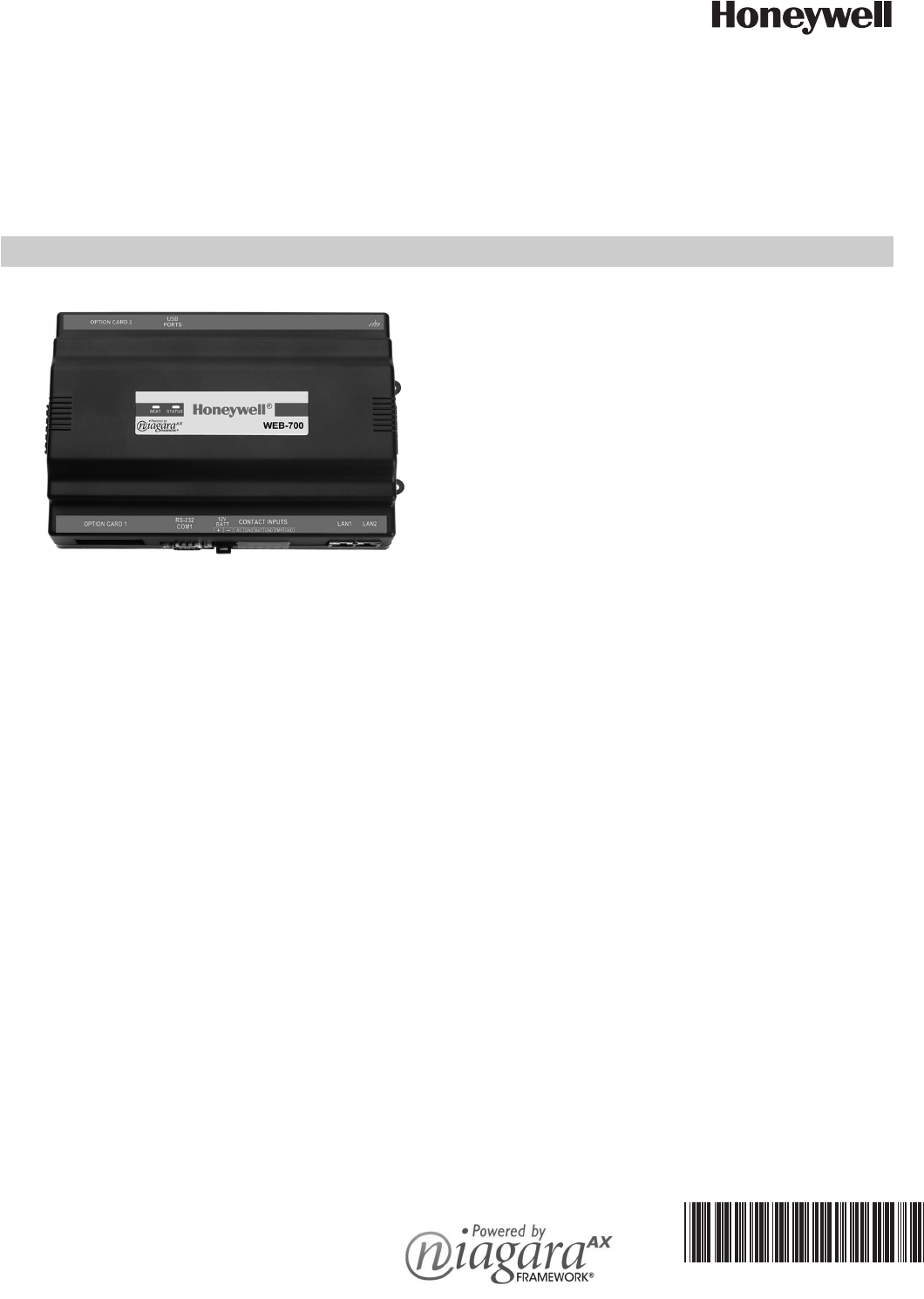
WEB-700 WEB-700-O CP-700 PRODUCT DESCRIPTION The WEB/CP-700 controller is a compact embedded processor platform using on-board Flash memory for backup, in an expandable DIN-modular package. Designed for use in commercial environments, the WEB/CP-700 runs the NiagaraAX Framework to provide integrated control, supervision, and network management solutions for wide variety of networked field devices. NiagaraAX-3.5 or later is required.
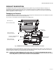
WEB-700 WEB-700-O CP-700 . NiMH battery pack and shield removed Removed option cards Main controller board DIN-mount base with screw tabs for panel mount Connector ports Fig. 2. WEB/CP-700 main controller board and 2 option cards uninstalled. As a 7 series controller, the WEB/CP-700 uses a PowerPC 440EPx processor, 1GB Flash storage, and 1 GB DDR-2 RAM. TCP/ IP access is via two standard Gigabit Ethernet ports. Serial communications ports (RS-232, RS-485) are standard.
WEB-700 WEB-700-O CP-700 Technical Specifications WEB/CP-700 PLATFORM • PowerPC 440Epx @ 667MHz processor (speed approximate due to spread spectrum clock). • 1GB on-board NAND Flash storage. • 1 GB DDR-2 333Mhz RAM (maximum Java Heap size 384MB). • Two (2) Gigabit Ethernet ports. • Standard RS-232 port. • 6-position end connector with isolated RS-485/15Vdc power (usable as a standard non-powered isolated RS-485 port, or to support remote I/O modules). • MiniPCI option slot, for optional NPB-WIFI-7 802.
WEB-700 WEB-700-O CP-700 PREPARATION Unpack the WEB/CP-700 and inspect the package contents for damaged or missing components. If damaged, notify the appropriate carrier at once and return any damaged components for immediate repair or replacement. See “Returning a Defective Unit” on page 25. • Included in this Package • Material and Tools Required Included in this Package Included in this package you should find the following items: • WEB/CP-700 controller.
WEB-700 WEB-700-O CP-700 WARNING A 120Vac or 240Vac circuit powers the NPB-PWR-UN-H power supply for the controller. 15Vdc input (DC only) to controller. Disconnect power before installation or servicing to prevent electrical shock or equipment damage. Make all connections in accordance with national and local electrical codes. Use copper conductors only. To reduce the risk of fire or electrical shock, install in a controlled environment relatively free of contaminants.
WEB-700 WEB-700-O CP-700 Physical Mounting The following information applies about physically mounting the unit. • You can mount the WEB/CP-700 in any orientation. It it not necessary to remove the cover before mounting. • Mounting on a 35mm wide DIN rail is recommended. The WEB/CP-700 unit base has a molded DIN rail slot and locking clip, as does the NPB-PWR-UN-H power supply module and any I/O expansion modules. Mounting on a DIN rail ensures accurate alignment of connectors between all modules.
WEB-700 WEB-700-O CP-700 To mount on DIN rail 1. Securely install the DIN rail with at least two screws, near the two rail ends. 2. Position the NPB-PWR-UN-H power supply module on the rail, tilting to hook DIN rail tabs over one edge of the DIN rail (Fig. 3). 3. Use a screwdriver to pry down the plastic locking clip, and push down and in on the module, to force the locking clip to snap over the other edge of the DIN rail. 4.
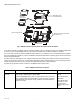
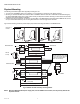
WEB-700 WEB-700-O CP-700 Board Layout Fig. 5 shows the location of connectors, option slots, and other features of the main board in the WEB/CP-700. For side views of communications ports and other features, see Fig. 6, page 13.
WEB-700 WEB-700-O CP-700 ABOUT EXPANSION OPTIONS The WEB/CP-700 provides for field-installable expansion using these types of options: • Option card — Install on connectors inside the WEB/CP-700 base unit. See About Option Cards, page 11. • Remote I/O modules — To wire to the WEB/CP-700’s right-side 6-pin connector. See About Remote I/O Modules, page 12. • MiniPCI option card — (future use). See About MiniPCI Cards, page 12.
WEB-700 WEB-700-O CP-700 OPTION CARD COM PORT ASSIGNMENTS COM port assignments for option cards installed in a WEB/CP-700 start at COM5, with Slot 1 evaluated first, then Slot 2. (COM1 and COM2 are always assigned to the onboard RS-232 and RS-485 ports, while COM3 and COM4 are reserved for slots.) INSTALLING AN OPTION CARD For option-specific details, see the mounting & wiring document that accompanies the particular option card. The following procedure provides a basic set of steps.
WEB-700 WEB-700-O CP-700 WIRING DETAILS See Fig. 5, page 10 to locate connectors and other components on the WEB/CP-700 controller. Make connections to the WEB/CP-700 in the following order. 1. 2. 3. Install any option board (LON, RS-485, RS-232, etc.) in the available option slots. See Installing an Option Card, page 12 for a procedure. For complete details, refer to the specific documentation that accompanied the option. Connect communications cables.
WEB-700 WEB-700-O CP-700 SERIAL There are two “RS” serial ports on the WEB/CP-700 base board. Each has a UART capable of operation up to 115,200 baud. At the bottom of the board (see Fig. 6, page 13) is an RS-232 port using an DB-9 plug (male) connector. On the right side of the unit is an isolated RS-485 port, using the bottom three terminals of a 6-position screw-terminal connector plug.
WEB-700 WEB-700-O CP-700 NPB-PWR-UN-H (remove cover) WEB/CP-700 Grounding lug Supplied earth grounding wire 20-pin connector not used L AC Input LN Line Grounding lug Neutral 120 or 240Vac 50–60 Hz Single Phase Earth Ground Fig. 7. Grounding and power wiring connections to NPB-PWR-UN-H module. Power Wiring There are two power options for the WEB/CP-700 controller: the NPB-PWR-UN-H power supply module (typical), or a NPBWPM-US (Wall Mount AC Adapter).
WEB-700 WEB-700-O CP-700 Wiring NPB-PWR-UN-H input power and earth ground. 1. Remove power from the AC circuit being wired to the NPB-PWR-UN-H—see previous . 2. Remove the NPB-PWR-UN-H cover. To do this, press in the four tabs on both ends of the unit, and lift the cover off. If the WEB/CP-700 is plugged into the unit, you may need to slide it away to get to the cover tabs. 3. Connect the supplied earth grounding wire to a nearby grounding point. See Fig. 7. 4.
WEB-700 WEB-700-O CP-700 Contact Inputs Three contact inputs (CIs) are available on a 6-position connector next to the 2-position external battery connector. CIs are typically used to monitor normally-closed (N.C.) alarm contacts, if available on a UPS and/or the “door tamper” switch of an enclosure. These CIs are unsupervised—no end-of-line resistors are required. Fig. 9 shows example wiring to all three CIs of the WEB/CP-700.
WEB-700 WEB-700-O CP-700 EXTERNAL 12V BACKUP BATTERY A 2-position connector provides support for an external 12V sealed lead-acid (SLA) type rechargable battery. For more details, see About the Backup Batteries, page 20. WEB/ CP-700 15Vdc power and backup battery passed through 6-position connector 712BNP 12V Sealed Lead Acid Backup Battery(ies) Fig. 10. Sealed lead-acid backup battery connection on WEB/CP-700. NOTE: The minimum wire size for battery connections is 18AWG (1.0mm2) for up to 4 ft. (1.
WEB-700 WEB-700-O CP-700 Wiring to Remote I/O Modules Wiring to remote I/O modules typically provides both 15Vdc power and 12V battery backup, along with RS-485 communications to the modules. See Fig. 11. Connect shield wire to ground at one end only WEB/CP-700 Power Supply (15V) and 12V Backup Battery is routed to remote IO modules using a 3-conductor with shield cable. Use the shortest wiring route possible for power wiring—star, tee, bus, and loop topologies are all permissible.
WEB-700 WEB-700-O CP-700 If after applying power, the STATUS LED goes out, or if the BEAT LED comes on (steady) and stays lit longer than 2 minutes, contact your local distributor for technical assistance. See also “About LEDs” on page 21. About the Backup Batteries A WEB/CP-700 controller has two different backup batteries: • An on-board NiMH battery pack, and • An optional external, sealed lead-acid, rechargeable backup battery (or batteries). See below.
WEB-700 WEB-700-O CP-700 ABOUT LEDS The WEB/CP-700 provides a number of LEDs on its main board. Only the Status and Heartbeat LEDs are visible on the cover. Checking other LEDs requires first removing the cover. LEDs include the following types: • • • • Status Heartbeat Debug Ethernet Ports For the location of LEDs on the main board, see Fig. 5, page 10. Status The green “STATUS” LED is located on the cover.
WEB-700 WEB-700-O CP-700 Required NiMH Battery Maintenance Battery life expectancy is a function of its discharge cycles (the number of discharges and their depth) and the ambient temperature of the battery during normal operation. In most applications, the NiMH battery should see relatively few discharges. Therefore, ambient temperature has more to do with the life expectancy of the battery than does any other factor.
WEB-700 WEB-700-O CP-700 NOTE: Dispose of the used NiMH battery properly. 4. 5. 6. 7. 8. 9. Unplug the NiMH battery from the main board connector (see Fig. 12). Using a 1/4" (6mm) nutdriver, unfasten and retain the two kep nuts that secure the metal battery bracket to the shield, and remove the shield and battery pack. Put the replacement battery into the metal shield, and refasten back into place on the shield, using the two kep nuts. Hand tighten with a nutdriver.
WEB-700 WEB-700-O CP-700 Replacing the WEB/CP-700 NOTE: Before handling circuit boards, discharge any accumulated static by touching a nearby earth ground. For details, see “Static Discharge Precautions” on page 7. To replace a WEB/CP-700 with a new replacement unit, proceed as follows: Replacing a WEB/CP-700 main controller board. 1. If possible, use the appropriate NiagaraAX software tool to back up the WEB/CP-700’s configuration to your PC. 2.
WEB-700 WEB-700-O CP-700 Returning a Defective Unit For proper credit on an in-warranty unit, ship the defective unit to Tridium within 30 days. NOTE: If the defective unit is under warranty, please follow return instructions provided in this section. If the unit is out of warranty, please discard any replaced part. Do not return an out-of-warranty WEB/CP-700 to Tridium.
WEB-700 WEB-700-O CP-700 CERTIFICATIONS Federal Communications Commission (FCC) This equipment generates, uses, and can radiate radio frequency energy, and if not installed and used in accordance with the instruction manual, may cause interference with radio communications.
WEB-700 WEB-700-O CP-700 TAB MOUNTING DIMENSIONS Measurements are in inches and (mm). DIN mounting is recommended over tab mounting. See Fig. 3, page 8. NOTE: Electronic and printed versions of this guide may not show the dimensions to scale. Verify all measurements before drilling. 0.170" Dia. (4.32) 0.98" (24.9) 0.1590" Dia. (4.04) 0.35" (8.9) 0.334" Dia. (8.5) 5.0" (127) 5.6" (142) 1.72" (43.7) 2.50" (63.5) 8.7" (221) Fig. 13. WEB/CP-700 tab mounting dimensions.
WEB-700 WEB-700-O CP-700 NPB-PWR-UN-H 3.48” (88.55) 2.50" (63.5) 8.125" (206) Distance between center of tabs from one unit to another unit Fig. 14. WEB/CP-700 with power supply attached. Automation and Control Solutions Honeywell International Inc. 1985 Douglas Drive North Golden Valley, MN 55422 customer.honeywell.com ® U.S. Registered Trademark © 2012 Honeywell International Inc. 95-7776—03 M.S. Rev. 03-12 Printed in U.S.A.