
Install Instructions


PP901A & B PRESSURE REDUCING VALVES
3-1/4
(83)
TOP VIEW
1-3/8
(35)
2-5/16
(59)
1-7/8 (48)
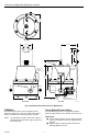
POSITION BRACKET
UPWARD OR DOWNWARD
1/4-IN NPT INLET
AND OUTLET
1/8-IN NPT
GAUGE
CONNECTION
1/8-IN NPT REMOTE
PILOT CONNECTION
(PP901B)
5/8 (16)
1-1/2 (38)
3-1/4 (83)
3-1/64
(77)
3-31/32
(101)
7/8
(23)
FRONT VIEW SIDE VIEW
OUT
EXHAUST
PORTS
IN
M12004
Fig. 1. PP901A & B Dimensions in Inches (Millimeters).
Calibration
Primary Reduced Pressure Setting
The PP901A & B is factory set for a regulated outlet
Use the following procedure to change the regulated
pressure of 18 psi (124 kPa). The safety relief valve is
(primary) outlet pressure to the desired system pressure.
factory set between 22 and 25 psi (152 and 172 kPa).
PP901A (Fig. 2)
NOTE: The following procedures require that a Gage is
Loosen locknut and turn pressure reducing adjust-
mounted in the 1/8-inch NPT gage connection on
ment screw clockwise to increase regulated outlet
the PP901A & B.
pressure.
Tighten locknut to maintain position of pressure
reducing adjustment screw.
95-2558
2