
Install Instructions


PP901A & B PRESSURE REDUCING VALVES
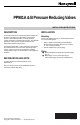
PP901B (Fig. 4)
Turn pressure reducing adjustment screw clockwise to
increase primary (lower) pressure. (For primary pressure,
the pressure reducing adjustment screw on the PP901B
does not have a locknut.)
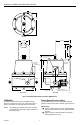
M12017
PRESSURE REDUCING
ADJUSTMENT SCREW
VENTLOCKNUT
PRESSURE REDUCING
ADJUSTMENT SPRING
PILOT
DIAPHRAGM
PILOT
VALVE SPRING
PILOT
VALVE
DIAPHRAGM
PRESSURE LINE
RESTRICTION
ASPIRATOR
TUBE
INLET
OUTLET
DIAPHRAGM
CHAMBER
DIAPHRAGM
WEIR
INTERNAL RELIEF
VALVE
INTERNAL RELIEF
VALVE SPRING
Fig. 2. PP901A Schematic.
Safety Relief Pressure Setting
Use the following procedure and refer to Fig. 3 and 4 to
change the safety relief valve pressure:
Using a spanner wrench or similar tool, turn safety
relief pressure adjustment screw inward as far as it
turns.
Adjust primary reduced pressure setting (per
Primary Reduced Pressure Setting procedure) until
it exceeds the desired safety relief pressure setting.
Slowly back off safety relief pressure adjustment
screw until Gage reads the desired safety relief
pressure setting.
Reset the pressure reducing adjustment screw for
the desired reduced pressure (per Primary Reduced
Pressure section).
RELIEF PRESSURE SPRING CUP AND
Fig. 3. PP901A & B Safety Relief Valve.
ADJUSTMENT SCREW GUIDE ASSEMBLY
RELIEF
VALVE
SPRING
SAFETY
RELIEF
VALVE
M12005
Secondary Reduced Pressure Setting
(PP901B Only)
Use the following procedure and Fig. 4 to change the
secondary (higher) pressure to the desired system
pressure.
NOTE: Perform the Primary Reduced Pressure Setting
procedure before this procedure.
Position switching mechanism to allow air passage
into switchover chamber.
Loosen locknut on pressure reducing adjustment
screw.
Rotate secondary pressure adjustment nut a few
turns in either direction until Gage reads desired
secondary pressure.
Tighten locknut to maintain position of pressure
reducing adjustment screw.
M12012
PRESSURE REDUCING
ADJUSTMENT SCREW
SWITCHOVER
PRESSURE
INLET
VENT
LOCKNUT
POINT "A"
PRESSURE REDUCING
ADJUSTMENT SPRING
DIAPHRAGM CUP
SWITCHOVER
CHAMBER
SWITCHOVER
DIAPHRAGM
PILOT
DIAPHRAGM
DIAPHRAGM
PRESSURE LINE ASPIRATOR TUBE
SECONDARY PRESSURE
ADJUSTMENT NUT
INLET
OUTLET
Fig. 4. PP901B Schematic with Switchover Chamber.
ENGINEERING DATA
Specifications
Models:
PP901A: For single pressure systems
PP901B: For two-pressure systems
Pressure Range:
Inlet: 45 to 150 psi (310 to 1034 kPa)
Outlet: 0 to 25 psi (0 to 172 kPa); factory set at 18 psi
(124 kPa)
Maximum Airflow:
10 scfm (0.05 m/s) at 18 psi (124 kPa)
Safety Pressure Relief:
Adjustment Range: 12 to 25 psi (83 to 172 kPa)
Factory Setting: 22 to 25 psi (152 to 172 kPa)
Capacity at 20 psi (138 kPa) outlet: 5 scfm (0.03 m/s)
Switchover (PP901B):
Two-position pilot switch actuated electrically or
pneumatically. Pressure relief feature exhausts
pressure difference.
Adjustment Range: 0 to 5 psi (0 to 35 kPa)
Factory Setting: 4.5 psi (31 kPa) ± .5 psi (3.5 kPa)
over low setting
3
95-2558