
Install Instructions


PP901A & B PRESSURE REDUCING VALVES
Connections:
Inlet and outlet: 1/4 in. NPT (female)
Gage: 1/8 in. NPT (female).
Remote Pilot (PP901B): 1/8 in. NPT (female)
Accessories:
14004205-002 Coalescing Filter
For PP901B switchover:
RP418A/B Electric-Pneumatic Relay or SP470A/B
Two-Position Pneumatic Switch
14003638-001 Mounting Kit
Operation
PP901A & B (Fig. 2)
A given pressure reducing adjustment screw setting
creates a force on the pilot diaphragm by tension on
pressure reducing adjustment spring. This force moves the
internal relief valve against the pilot valve and causes the
pilot valve to move downward and off its seat.
As high pressure air enters the valve through the INLET, it
passes between the weir and the diaphragm and onward
to the valve OUTLET. At the same time, air travels through
the open pilot valve, diaphragm pressure line, and
diaphragm chamber until its pressure equals that of the
inlet pressure.
As downstream pressure increases, air pressure builds
beneath the pilot diaphragm through the aspirator tube
connection with the downstream line.
Downstream pressure and air pressure beneath the pilot
diaphragm continue to rise. The force acting on the pilot
diaphragm overcomes the force of the pressure reducing
adjustment spring. This action forces the pilot diaphragm
and internal relief valve upwards and allows the pilot valve
to return to its seat.
With the pilot valve on its seat, air in the diaphragm
pressure line cannot escape and is trapped in the line. Air
continues to enter the diaphragm chamber through the
small restriction in the diaphragm and pressure builds up
in the diaphragm chamber. This pressure forces the
diaphragm against the weir and cuts off air flow through
the valve.
A small reduction in the downstream pressure now causes
the pilot diaphragm to force the pilot valve off its seat. This
allows main line pressure to leak from the diaphragm
chamber through the diaphragm pressure line and pilot
valve to the downstream side of the system. When this
side of the system reaches its preset pressure, the pilot
diaphragm moves upwards and closes the pilot valve.
If the pilot diaphragm continues to move upward from
over-pressure in the downstream line, it allows the internal
relief valve spring to force the internal relief valve off its
seat and bleeds the downstream pressure to the atmo-
sphere through the vent.
Setting the Safety Relief Pressure (Fig. 3).
If excessive downstream pressure builds up inside the
valve it acts against the safety relief valve. If pressure
becomes high enough the force of the air pressure on the
safety relief valve overcomes the force of the safety relief
valve spring and opens the safety relief valve. With the
safety relief valve open any excessive pressure is bled
from the valve to the atmosphere.
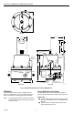
PP901B Switchover Operation (Fig. 4)
Air from the switching mechanism enters the airtight
switchover chamber through the switchover pressure inlet.
This air pressure acts on the diaphragm cup and
switchover diaphragm to overcome the force of the
pressure reducing adjustment spring. As the switchover
diaphragm and switchover cup move downward, they
further compress the pressure reducing adjustment spring.
At the same time the flow of air creates a low pressure in
the aspirator tube and in the chamber beneath the pilot
diaphragm. This low pressure aids in moving the dia-
phragm cup down and speeds up the switchover opera-
tion. The downward movement of diaphragm cup is
stopped when the secondary pressure adjustment nut
comes in contact with the valve body at point “A”.
The combination of the forces of the two pressures (the
pressure reducing adjustment spring and the controlled
pressure on the switchover diaphragm) require greater
pressure (from the downstream line acting below the pilot
diaphragm) to close the pilot valve. These pressures
maintain a higher pressure in the downstream line during
this phase of operation.
Application(s)
The PP901B includes a 1/8-inch NPT remote pilot
connection to handle the switchover from one pressure to
another. The remote pilot can be a two-position switch that
is actuated electrically or pneumatically. For example, a
RP418A/B Electric-Pneumatic Relay or SP470A/B Two-
Position Pneumatic Switch can connect to this mounting
boss to introduce the air pressure that switches the
PP901B from one pressure to another (Fig. 5).
TO ELECTRIC
CONTROL CIRCUIT
RP418A/B
HIGH PRESSURE LINE
PP901B
SP470A/B
EXHAUST
PLUG
HIGH PRESSURE LINE
PP901B
9
7
6 8
M12011
Fig. 5. PP901B Switchover Piping.
Home and Building Control
Home and Building Control
Helping You Control Your World
®
Honeywell Inc.
Honeywell Limited-Honeywell Limitée
Honeywell Plaza
155 Gordon Baker Road
P.O. Box 524
North York, Ontario
Minneapolis, MN 55408-0524
M2H 2C9
95-2558 L.A. 10-96 Printed in U.S.A