
Q335 Installation Instructions


XX-XXXX—X
2
Q335 QUICK DROPOUT THERMOCOUPLE
Home and Building Control
Honeywell Limited-Honeywell Limitée
155 Gordon Baker Road
North York, Ontario
M2H 3N7
69-1191 G.S. 5-98
Home and Building Control
Honeywell Inc.
Honeywell Plaza
P.O. Box 524
Minneapolis, MN 55408-0524
Printed in U.S.A. on recycled
paper containing at least 10%
post-consumer paper fibers.
www.honeywell.com
Install New Thermocouple
1. Hold the pilot burner assembly with one hand.
With the other hand, insert the new thermo-
couple in the pilot burner, pushing the thermo-
couple into the pilot burner until it stops. See
Fig. 1.
2. Engage attachment nut threads and firmly
tighten the nut.
3. Connect the female end of the thermocouple
lead to the power unit of the VS8520.
4. Engage the attachment nut threads and, using a
wrench, tighten 1/4 turn beyond finger tight.
Important:
This is an electrical connection. Make sure
that all connections are clean and tight for
proper operation.
STARTUP AND CHECKOUT
Pilot Gas and Lighting Procedure
1. Turn on gas supply to appliance. Leave thermo-
stat set below room temperature.
2. Relight appliance following the appliance
manufacturer’s instructions. If the
manufacturer’s instructions are not available
proceed as follows to light the pilot.
NOTE: The pilot burner on some appliances is lit
by a piezo-electric current (the pilot
burner has an electrode as shown in
Fig.1). If your appliance has an electrode
for lighting the pilot burner, follow the
appliance manufacturer’s instructions. Do
not use the instructions provided below.
a. Turn the VS8520 gas control knob
counterclockwise to the PILOT position,
then push the knob down and hold it in
position.
b. While holding the knob down, light the
pilot burner. Continue to hold down the
knob until a strong flame is present
(approximately 60 seconds).
c. Release the knob; the pilot should con-
tinue to burn.
d. Turn the gas control knob counterclock-
wise to the ON position.
e. Turn up the thermostat to call for heat.
The main gas valve should open and the
main burner should ignite.
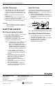
Adjust Pilot Flame
The pilot flame should envelop 3/8 to 1/2 in. (10 to 13
mm) of the tips of both the thermocouple and the
thermopile. Refer to Fig. 2. If necessary, adjust the
pilot flame as follows:
1. Remove the pilot adjustment cover screw.
2. Turn the inner pilot adjustment screw clockwise
to decrease or counterclockwise to increase the
pilot flame.
3. Replace the pilot adjustment screw cover.
Fig. 2. Tip of thermocouple must be in pilot flame.
Check Safety Shutdown Performance
1. Turn the thermostat below room temperature.
The main burner should go out.
2. Extinguish the pilot flame. Make sure that pilot
gas flow stops within 30 seconds.
3. Relight pilot burner by following the
manufacturer’s instructions.
THERMOCOUPLE
PROPER
FLAME
ADJUSTMENT
3/8 TO 1/2 INCH
(10 TO 13 MILLIMETERS)
M12847