
Install Instructions
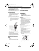
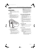
Table Of Contents

Q3450, Q3453 AND Q3480 SMARTVALVE™ SYSTEM PILOT BURNERS
69-0708—3 2
5. Do not impinge pilot flame on adjacent parts. Do
not impinge main burner flame on pilot burner.
6. Do not expose pilot flame to falling scale that could
impair main burner ignition.
7. Do not expose pilot burner to main burner rollout
while igniting or extinguishing.
8. Do not expose pilot flame to drafts that push or pull
pilot flame away from the igniter-flame rod.
Connect Pilot Gas Tubing
1. Cut tubing to desired length and bend as
necessary for routing to pilot burner. Do not make
sharp bends or deform tubing. Do not bend tubing
at control after compression nut is tightened
because this can result in gas leakage at
connection.
2. Square off and remove burrs from end of tubing.
3. Push tubing into compression nut clearance hole
until tubing bottoms.
NOTE: When replacing an ignition system control, cut
off old compression fitting and replace with new
compression fitting provided with new pilot
burner. Never use old compression fitting
because it might not provide a gas-tight seal.
See Fig. 3.
Fig. 3. Always use new compression fitting.
4. While holding tubing all the way in, engage threads
and turn until finger tight.
5. Using a wrench, turn compression nut one turn
beyond finger tight. DO NOT OVERTIGHTEN.
6. Connect the other end of the tubing to ignition sys-
tem control according to ignition system control
manufacturer instructions.
Wire Pilot Burner to Ignition System
Control
1. Mount the igniter-flame rod assembly on the pilot
burner.
2. Connect the igniter-flame rod assembly keyed plug
connector to its mating terminal block, labeled
IGNITER, on the SV94/SV95/SV96/SV98XX.
3. Use ceramic or plastic standoff insulators as
necessary to prevent cable from contacting metal
surfaces.
STARTUP AND CHECKOUT
Perform Gas Leak Test
WARNING
Fire or Explosion Hazard.
Can cause severe injury, death or property
damage.
Check for gas leaks with soap and water solution
any time work is done on a gas system.
Gas Leak Test:
1. Make sure that gas supply is turned on at the
appliance service valve.
2. Paint pipe connections upstream of pilot burner
with rich soap and water solution. Bubbles indicate
gas leak.
3. If leak is detected, tighten pipe connections.
4. Set thermostat to call for heat to light main burner.
5. With main burner in operation, paint pipe joints
(including adapters) and ignition system control
inlet and outlet with rich soap and water solution.
6. If another leak is detected, tighten adapter screws,
joints, and pipe connections.
7. Replace part if leak can not be stopped.
Adjust Pilot Flame
The pilot flame should envelop approximately 3/8 in.
(10 mm) of the sensor tip. See Fig. 4.
To adjust pilot flame:
1. Turn off system by setting thermostat below the
temperature to call for heat.
2. Disconnect lead to MV terminal on the
SV94/SV95/SV96/SV98XX.
3. Light pilot by setting the thermostat to call for heat.
4. Remove the pilot adjustment cover screw from the
gas control.
5. Turn inner pilot adjustment screw clockwise to
decrease or counterclockwise to increase pilot
flame.
6. Always replace pilot adjustment cover screw and
tighten firmly after completing adjustment to assure
proper operation.
Fig. 4. Sensor tip must be in pilot flame.
PILOT BURNER BODY ON
BRACKET OF PILOT BURNER
TIGHTEN NUT ONE TURN
BEYOND FINGER TIGHT
COMPRESSION FITTING
BREAKS OFF AND CLINCHES
TUBING AS NUT IS TIGHTENED
TO IGNITION
SYSTEM CONTROL
M2687
A
3/8 INCH
(10 mm)
PROPER FLAME
A
DJUSTMENT
IGNITER
M9049
SENSOR
69-0708-3.fm Page 2 Monday, May 10, 2004 9:11 AM