
Submittal Sheet
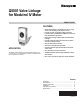

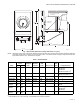


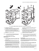

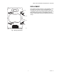

Table Of Contents

Q5001 VALVE LINKAGE FOR MODUTROL IV MOTOR
63-2425—01 6
motor bracket. It may be necessary to squeeze the
motor auxiliary end of the linkage bracket slightly to align
the mounting holes.
3. Start all four motor bolts, then tighten the bolts on the
power end first, pulling the motor snugly to the linkage
motor bracket and compressing the linkage springs.
4. Tighten the auxiliary end mounting bolts.
5. If the cam is pointing upward, remove motor wiring cover
(on nonspring return motors) and raise the linkage slide.
6. Tilt the motor power end face down about 30° and slide
motor and cam assembly into linkage opening at an
angle to align one power end bolt hole. Make sure that
the cam is between the linkage rollers. See Fig. 5(A).
Fig. 4. Stem force pin position selection.
FRONT SLIDE PLATE
REAR SLIDE PLATE
SET SCREW
CLIP IN SLOT
STEM BUTTON
VALVE STEM
M2774
STEM FORCE PINS
PIN LOCKED POSITION
PIN REMOVAL POSITION
MODUTROL IV
MOTOR CLIP SLOT
MODUTROL IV
ANTI-SPIN
CLIP SLOT
MODUTROL III MOTOR
CLIP SLOT
CLIP RETAINING
LEVER
CLIP MUST ENGAGE SLOTS ON STEM BUTTON AND
REAR SLIDE PLATE.
CHOOSE TOP SLOT IN SLIDE FOR MODUTROL IV OR
BOTTOM SLOT FOR MODUTROL III
1
2
1
2
SLIDE
PUSH HERE