
Submittal Sheet
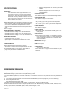
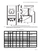
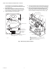

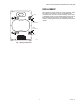

Table Of Contents

Q5001 VALVE LINKAGE FOR MODUTROL IV MOTOR
3 63-2425—01
Fig. 1. Approximate Q5001 Valve Linkage dimensions in in. [mm].
NOTE: High torque spring return motor shown. Medium torque spring return and nonspring return motors require less clearance
on auxiliary end of motor. Linkage for 3/4 in. stroke and 1-3/8 in. valve bonnet shown. Linkage for large valve bonnet and
larger stroke maximum 12 in. of clearance is required.
a
If valve stroke is not 3/4 in. [19 mm], a merchandise cam must be purchased.
b
If valve stroke is not 1-1/2 in. [38 mm], a merchandise cam must be purchased.
Table 1. Standard Models.
Model
Valve Stem
Force
Lift Adjust-
ment
Bonnet
Connect
Bonnet
Size
(O.D.) Stem Connect
Anti-
Spin Linkage Replaced(lb) N
Q5001A1006 80 355.9 3/4 fixed Setscrew 1-3/8 Button and clip No Q618A1016,
Q618A1032,
Q618A1040,
Q618A1014, Q601L, M
a
Q5001A1014 160 711.7 3/4 fixed Setscrew 1-3/8 Button and clip No Q618A1008,
Q618A1024, Q601J, K
a
Q5001A1022 320 1355 3/4 fixed Setscrew 1-3/8 Button and clip No
Q601Q
a
Q5001B1004 160 711.7 1-1/2 fixed Setscrew 1-7/8 Button and clip Yes
Q601E
b
Q5001B1012 320 1355 1-1/2 fixed Setscrew 1-7/8 Button and clip Yes
Q601P
b
Q5001D1000
Tradeline
80,
160
355.9-
711.7
3/4 fixed Setscrew 1-3/8 Button and clip Yes
Q601J, K, L, M
a
Q618A
Q5001D1018
Tradeline
160,
320
711.7-
1355
3/4 fixed Setscrew 1-3/8 Button and clip Yes Q601J, K, Q
Q618A1008
a
,
Q618A1024
Q5001D1026
Tradeline
160,
320
711.7-
1355
1-1/2 fixed Setscrew 1-7/8 Button and clip Yes
Q601E, P
b
O
PE
N
C
L
OS
E
D
MOTOR NOT INCLUDED
IN LINKAGE
10
[260]
1
4
27
64
1 [36]
13
16
5 [148]
29
32
6 [176]
25
32
8 [223]
-10
-[267]
1
2
(POWER END
OF MOTOR)
1/4 X 20 X 1
MOUNTING
BOLTS
M3443A