
Submittal Sheet
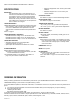
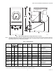
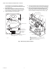

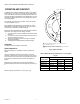
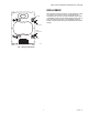

Table Of Contents

Q5001 VALVE LINKAGE FOR MODUTROL IV MOTOR
63-2425—01 4
a
Merchandise cam required.
a
Refer to Modutrol Motor specifications to select motor with equal or greater torque. Modutrol IV Motors are available with 25 and
60 lb-in. outputs (spring return); 35, 75, 150 and 300 lb-in. (nonspring return).
b
The 320 lb stem force linkage must be used with a 300 lb-in. motor.
INSTALLATION
WHEN INSTALLING THIS PRODUCT…
1. Read these instructions carefully. Failure to follow them
could damage the product or cause a hazardous condi-
tion.
2. Check the ratings and description given on the product
to make sure the product is suitable for your application.
3. Installer must be a trained, experienced service techni-
cian.
4. After installation is complete, check out product opera-
tion as provided in these instructions.
5. Refer to the instruction sheet packed with the valve body
for information on installing the valve.
6. Refer to the instruction sheet packed with the Modutrol
IV Motor for wiring diagrams and additional installation
information for the motor.
Location
Select a location that allows ample clearance for adjustment
and maintenance. Allow at least 4 in. [102 mm] above the
linkage to remove the valve assembly for maintenance.
Linkages may be mounted in a variety of positions. The 320 lb
stem force linkage must be assembled to a 300 lb-in. Modutrol
IV Motor. The linkage and motor may be rotated 360 degrees
around the valve stem. However, in all installations, the motor
shaft must be horizontal to ensure proper gear train lubrication
and the valve stem must be above horizontal.
Table 2. Valve-Linkage Selection Guide.
Honeywell
Valve Type
Valve
Body Style
Pipe
Size (in.) Linkage
Bonnet
Size (O.D.)
Lift
(in.)
V5011A 2-way Flanged 2-1/2, 3 Q5001A, D 1-3/8 3/4
V5011A, B 2-way Flanged 4, 5, 6 Q5001B, D 1-7/8 1-1/2
V5011F 2-way Screwed 1/2, 3/4, 1, 1-1/4, 1-1/
2, 2, 2-1/2, 3
Q5001A, D 1-3/8 3/4
V5011G 2-way Screwed 1/2, 3/4, 1, 1-1/4,
1-1/2, 2, 3
Q5001A, D 1-3/8 3/4
V5013B 3-way mixing Flanged 2-1/2, 3 Q5001A, D 1-3/8 3/4
V5013B 3-way mixing Flanged 4, 5, 6 Q5001B, D 1-7/8 1-1/2
V5013C 3-way diverting Flanged 2-1/2, 3 Q5001A, D 1-3/8 3/4
V5013C 3-way diverting Flanged 4, 5, 6 Q5001B, D 1-7/8 1-1/2
V5047A 2-way Screwed 1, 1-1/4, 1-1/2 Q5001A, D 1-3/8
9/16
a
V5047A 2-way Screwed 2 Q5001A, D 1-3/8 3/4
V5051A 2-way Flanged 2-1/2, 3, 4, 5, 6 Q5001B, D 1-3/8 1-1/2
Table 3. Cam Selections Available.
Cam
Number Type Lift
Required Torque
a
(lb-in.)
Application
80 lb stem
force
160 lb
stem
force
320 lb
stem
force
b
220858A Custom 9/16 in. 25 50 100 V5047A, 1 in. to 1-1/2 in.
220861A Standard 3/4 in. 25 50 100 V5011/V5013, 1/2 in. to 3 in.;
V5047A, 2 in.
220863A Custom 1 in. 30 60 120
220864A Custom 1-1/8 in. 30 60 120
220865A Custom 1-1/4 in. 50 100 200
220867A Standard 1-1/2 in. 50 100 200 V5011/V5013, 4 in. to 6 in.