
Submittal Sheet
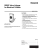
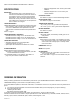
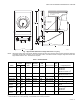
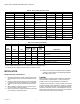
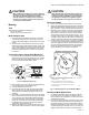
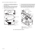

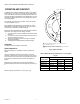
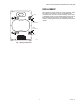

Table Of Contents

Q5001 VALVE LINKAGE FOR MODUTROL IV MOTOR
5 63-2425—01
CAUTION
When mounting the linkage to the valve, make sure
that the set screws holding the valve linkage to the
valve body are properly tightened to prevent
improper operation or damage to the equipment.
The torque for tightening these screws should be
in the range of 72 to 120 lb-in.
Mounting
Tools
Tools required for installing the linkage are:
• 5/32 in. hex wrench.
• 7/16 in. open end or box end wrench.
Mount Linkage to Valve
1. Loosen the two valve bracket set screws, if necessary,
and slide the linkage over the valve stem and bonnet
until the valve bracket rests on the shoulder of the valve
bonnet.
2. Tighten the two valve bracket set screws to secure the
linkage to the valve. Make sure that the set screws hold-
ing the valve linkage to the valve body are properly tight-
ened to prevent damage to the equipment. The torque
for tightening these screws should be in the range of 72
to 120 lb-in.
Connect Valve Stem to Linkage Slide (Modutrol IV)
1. Position the stem and stem button so that the sides are
parallel to the entry of the anti-spin clip (Fig. 2). This will
allow using the clip without disassembling and turning
the stem and button as described in step 5.
Fig. 2. Installing anti-spin clip
2. Move the slide up or down until the top slot matches the
slot in the stem button as indicated in Fig. 4.
3. Push clip retainer lever to the left.
4. Insert clip into upper slot until clip stops reach linkage
slide front plate. The clip must engage the slot on the
stem button and rear slide plate slot for proper valve
operation.
5. OPTIONAL: To insert the anti-spin clip, push clip retainer
lever to the left, and insert the anti-spin clip in the middle
slot. Insert until clip contacts linkage slide front plate. If
clip will not fully insert, remove anti-spin clip and stem
button clip. Turn stem and button until the button sides
are parallel to the entry of the anti-spin clip. Replace
stem button clip and anti-spin clip.
6. Release clip retainer lever. When slide is moved, entire
slide and valve stem should move up and down together.
CAUTION
When mounting the cam to the motor, make sure
that the set screws holding the cam to the motor
shaft are properly tightened to prevent damage to
the equipment. The torque for tightening these
screws should be in the range of 72 to 120 lb-in.
Mount Cam to Motor
1. Place 1/2 in. diameter plastic washer on motor shaft.
2. Select cam appropriate to linkage and valve combination
(standard model Q5001 Linkages include only one cam).
Refer to Table 3 on page 4 for alternate cam selections.
3. Determine correct position of the cam to provide proper
valve operation. To achieve normally closed operation
(stem down to close valve), the cam must be mounted
on the power end of the motor as shown in Fig. 3. For a
normally closed motor, the shaft rotates clockwise on an
increase in signal, lifting the valve stem. If normally open
operation is desired, install the cam rotated 180 degrees.
4. Loosen the two cam set screws, if necessary, and slide
the cam over the motor shaft to the stops and tighten the
set screws. Make sure the set screws holding the cam to
the motor shaft are properly tightened to prevent dam-
age to the equipment. The torque for tightening these
screws should be in the range of 72 to 120 lb-in.
Fig. 3. Mounting the cam on the Modutrol Motor
Mounting the Motor Without Power
1. On Tradeline selectable stem force models, select the
proper hole for the pin to obtain the desired closeoff
force needed for your application. The stem force holes
are labeled on the slide.
2. If the cam is pointing upward, go to Step 5. If the cam is
pointing downward, slide motor and cam assembly into
the linkage, aligning the motor mounting holes with the
linkage mounting holes and mount the motor on the link-
age bracket using the enclosed 1/4-20 x 1 in. bolts. The
linkage will raise the motor power end off the linkage
STEM BUTTON
MIDDLE
SLOT
ANTI
SPIN CLIP
M3480
REAR SLIDE
PLATE
FRONT SLIDE
PLATE
STEM BUTTON
ANTISPIN
CLIP
TOP VIEW
POWER END
M3445A
VIEW IS FROM POWER END, NORMALLY CLOSED
SPRING RETURN MOTOR.
CAM IS IN NORMAL ORIENTATION FOR NORMALLY
CLOSED (STEM DOWN TO CLOSE VALVE) OPERATION.
DOTTED LINES SHOW INSTALLATION FOR NORMALLY
OPEN OPERATION.
1.
2.
3.
SET
SCREWS