
Submittal Sheet
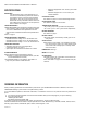
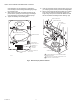

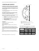
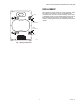
Table Of Contents

Q5001 VALVE LINKAGE FOR MODUTROL IV MOTOR
7 63-2425—01
Fig. 5. Mounting Modutrol Motor to Q5001 Valve Linkage with cam pointing up.
7. Install bolt but do not tighten.
8. Rotate motor to align the other power end bolt hole (B)
and install second bolt, but do not tighten at this time.
9. Install auxiliary end mounting bolts and tighten (C), pull-
ing auxiliary end of motor snugly to linkage motor
bracket. It may be necessary to squeeze the motor auxil-
iary end of the linkage bracket slightly to align the mount-
ing holes.
10. Tighten power end mounting bolts.
NOTE: If motor and linkage are assembled without power,
the operation and checkout must be performed to
guarantee proper performance.
Mounting the Motor With Power Available
(Optional Means)
1. For easier assembly, run the motor to mid-stroke. Refer
to Modutrol Motor Specification for instructions on oper-
ating the motor.
2. OPTIONAL: Remove the upper force pin, push up the
lever arm as indicated in Fig. 4 and replace pin in posi-
tion to hold the lever arm away from the opening to allow
the cam and motor assembly to slide into position easily.
Repeat for the lower force pin. The lower force pin must
be placed in the outer hole, because the valve stem but-
ton limits the lever movement, preventing inner hole
alignment. Refer to Fig. 4.
3. Slide motor and cam assembly into opening, align the
motor mounting holes with the linkage mounting holes
and assemble the motor to the motor brackets using the
enclosed 1/4 - 20 x 1 in. bolts, but do not tighten. It may
be necessary to squeeze the motor auxiliary end of the
Q5001 Valve Linkage slightly to align the mounting
holes. See Fig. 1.
4. If levers were held out of the way in Step 2, remove the
force pins and allow levers to return to operating posi-
tion. Insert pins in the proper hole for the pin to obtain the
desired closeoff force needed in your application and
rotate to the locked position as shown in Fig. 4.
5. Tighten the 1/4 x 20 x 1 in. motor bolts.
NOTE: Both upper and lower stem force pins must be in the
same force hole location to make sure that proper
seal off force for the valve is applied. Failure to lock
arms in location with stem force pins will prevent the
valve from closing.
Final Assembly
After checkout (see “Operation and Checkout” on page 8),
install the position indicator on the cam. The center of the
indicator should coincide with the center of the motor shaft, see
Fig. 3. This will allow the indicator to show position of the valve
through the cover of the motor.
The indicator is shipped with arrow label for normally closed
valve operation. On a normally open valve, install the spare
indicator label at 180° to the original label.
Place the cover on the linkage by positioning the cover with the
hole centered over the indicator, label oriented upwards. Press
the cover over the linkage frame until the indents snap into
place on the frame. Run the valve through two operating cycles
to make sure that no binding occurs during operation.
A
B
C
M2773