
Product Overview


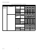


Table Of Contents

GLOBE VALVE LINKAGES
13 38-00020—01
INSTALLATION
When Installing this Product...
1. Read these instructions carefully. Failure to follow them
could damage the product or cause a hazardous
condition.
2. Check the ratings given in the instructions and on the
product to make sure that the product is suitable for your
application.
3. Installer must be a trained, experienced service
technician.
4. After installation is complete, verify product
operation as provided in these instructions.
Location
Select a location in which the valve, linkage, and motor will be
within the environmental and ambient temperature ratings. See
the specifications section.
NOTE: Allow approximately 12 in. clearance above the valve
bonnet for installation and servicing.
Mounting
IMPORTANT
1. Ensure the valve stem stroke matches the Q5024
linkage. See Table 1.
2. Mounting the Q5024 on a non-Honeywell valve
requires the correct bonnet and stem adapter. See
Table 4.
Installation
1. De-energize the valve and if needed, take it out of ser-
vice.
2. Remove the existing actuator from the valve.
3. Remove existing stem adapter if used.
4. Clean the threads on the valve
5. For threaded stems, run a jam nut (if used) all the way
down the stem. Thread the stem adapter firmly onto the
stem. Then turn the jam nut back up until it hits the
adapter and tighten the two in place.
6. If a bonnet adapter is used:
a. If threaded, firmly screw the adapter onto the valve
bonnet.
b. If not threaded, tighten the adapter set screws into
the valve bonnet.
7. Slide the linkage box over the bonnet adapter on the
valve. Insert the two long bolts through the hole at the
bottom of the linkage, lined up with the notch on the
adapter. Once through, attach washer, lock washer, and
tighten firmly.
8. Loosen the two 5mm Allen head screws on the stem clip
and slide it over the notch on the stem adapter. Then
tighten the two screws.
9. Verify that the valve stem stroke direction and the actua-
tor rotation direction are properly related. For example,
assume a spring return actuator and a 2-way, stem down
to close, normally-closed valve are used together. With
an unpowered actuator, the valve should be fully closed.
To accomplish this rotate the actuator arm on the linkage
fully counterclockwise. This moves the valve stem fully
downward so that when the actuator turns counterclock-
wise the valve will close.
10. Mount the actuator onto the actuator arm approximately
five degrees from its end stop with the valve fully seated.
This ensures that the actuator closes the valve before it
reaches its end-stop.
11. Place the anti-rotation pin into the bracket slot (see step
5), and slide into the notch on the rear of the actuator.
Next secure the actuator to the actuator arm and finish
by tightening the anti-rotation nut. Complete installation
with wiring the actuator.
LINKAGE INSTALLATION
1. Remove any existing linkages then screw the jam nut
and stem adapter onto the valve stem.
2. Screw the bonnet adapter onto the valve neck and
tighten.
M35308
STEP 1
JAM NUT
(IF USED)
STEM
ADAPTER
M35309
STEP 2