
Product Overview


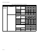


Table Of Contents

GLOBE VALVE LINKAGES
38-00020—01 14
3. Attach the stem adapter to the mounting clips and
tighten the screws.
4. Use two bolts to secure the valve to the linkage.
5. Typical installation of direct coupled actuators.
CHECKOUT
After installing the linkage and the actuator, proceed as follows:
1. Apply power to the actuator.
2. Cycle the valve through at least one complete stroke to
ensure proper operation.
3. Ensure that the valve seats before the actuator reaches
the stroke end.
NOTE: For 3-way valves it is important to make sure
that the plug sits properly on both the upper and
the lower seats before the actuator reaches
either end of its full stroke.
4. If the valve does not travel or seat properly and is
installed correctly, check Table 3. Ensure the valve, actu-
ator, and linkage combination is correct for your applica-
tion.
5. If the preceding troubleshooting steps do not locate the
problem, check both the actuator and valve individually
(see Checkout sections of the device instructions). For
example, the actuator stroke may be impeded or the
valve stem adapter height may be out of adjustment.
6. If the valve and actuator operate properly but the valve,
actuator, and linkage combination does not, replace the
linkage.
CAUTION
Follow these instructions carefully when installing
this product; failure to follow these instructions
and the instructions of other products used with
this linkage may result in damage to the product or
personal injury. Use caution in removing pneumatic
actuators from valves as the springs may be under
pressure. Installer must be a trained, experienced
technician.
M35310
STEP 3
M35311
STEP 4
M35439
STEP 5